Terry, your front end voltages look good - things seem to go wrong from the TIS stage onward.
I am a bit concerned about the voltage you are reading across R8 (this is the BE voltage of Q20 BC557C). You are showing 1.92V which looks like it may either be blown or leaky - so Q3 is conducting most of the TIS current, or you have oscillation.
If in fact you are reading 1.92 across Q20 BE junction, I would replace that as a first step. Double check Q3 (BC847C)
You should easily be able to adjust the output offset to 0.
Can you check that C14 is in place and the correct value as well.
NB when doing these readings, make sure the input is disconnected AND the input is shorted to 0V. J2 must also be linked (i.e. shorted) as well). This is a DC coupled amplifer, so any DC offset on the input will be amplified and presented at the output. The presumtion with this design is that the pre-amp has zero offset or it its output is capacitively coupled.
Last edited:
I sim the nx-amp and get spec which is almost same that wrote on Bonsai's website. I read his website and found many things valuable. Thank you, Bonsai.
May I write your nx-amp in my blog (using Indonesia language), base on my simulation?
May I write your nx-amp in my blog (using Indonesia language), base on my simulation?
Hi Andrew,
Yes, I noticed the 1.92V on the BE of Q20, that is why I noted it. I replaced it and there was no change. Then I checked the VBE of Q3 and it looked OK. I will try replacing the stinking SMD again and see if it helps. This is probably my last SMD amp. C14 is installed. Like I said, I'm stumped.
Yes, I shorted the input and J2.
Thanks, Terry
I sim the nx-amp and get spec which is almost same that wrote on Bonsai's website. I read his website and found many things valuable. Thank you, Bonsai.
May I write your nx-amp in my blog (using Indonesia language), base on my simulation?
No problem Bimo - you are welcome.
Hi Andrew,
Yes, I noticed the 1.92V on the BE of Q20, that is why I noted it. I replaced it and there was no change. Then I checked the VBE of Q3 and it looked OK. I will try replacing the stinking SMD again and see if it helps. This is probably my last SMD amp. C14 is installed. Like I said, I'm stumped.
Yes, I shorted the input and J2.
Thanks, Terry
If you lift R1 (10k SMD) , what does the output voltage read? Lets try this, because it may help us identify the problem more easily.
The Q20 BE voltage almost seems like you may have a BC547C instead of a BC557C
Can you measure the CE boltage on Q3 also?
Are R41 and R42 linked out - i.e. shorted?
Do you have a scope?
Dont knock SMD - they are great!
Last edited:
If you lift R1 (10k SMD) , what does the output voltage read? Lets try this, because it may help us identify the problem more easily.
Didn't lift it yet. R1 is through hole on my board
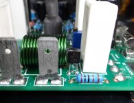
The Q20 BE voltage almost seems like you may have a BC547C instead of a BC557C
BC557C see pic
Can you measure the CE boltage on Q3 also?
.710V across Q3 CE
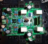
Are R41 and R42 linked out - i.e. shorted?
Yes with SMD 0R. see pic 2
Do you have a scope?
Yes. I'm not an expert with it but if you tell me what to look for I can do that.
Dont knock SMD - they are great
I'm not a fan. One of those little gnat larvas in Q3 took off when I squeezed a little too hard.. Never could find it. I should have bought a bag full I guess! I did buy two spares. Looks like that may have not been enough.
Attachments
What do I look for? I have heard this suggested before but never described the steps to do it.
Thanks. Terry
PS I hooked up the other board and get the same results so whatever error it is I have it on both boards.
Edit; One thing I have been meaning to ask about is when testing for voltages, I have my ground lead attached to ground and when I touch the positive lead to the base or collector of Q6 or Q7 the bias soars and the voltage drops at those locations. It doesn't do that if I measure across the B/E only if I touch them with the probe while the ground lead is connected to circuit ground.
Last edited:
I have not seen the problem of the bias increasing when measuring between the base of Q6 or Q7. These are tied to the plus rails with 1 K resistors, and if the DVM has a high input impedance ( usually 10 M Ohm) it should not affect it. It sounds to me like you have oscillation.
To look at this with your scope, connect the ground pin to 0 V and then connect th probe to the output. Turn the scope gain up to max. You should get a straight line across the display with the input shorted.
I will pull my nx-Amp lid off later today and take some measurements also. I'd really like get your amps up and running.
OK I hooked up the scope. With the gain all the way up I get just a slightly fat line. If I turn the dial all the way up to 100mhz and fine tune it I can see a very thin tight sine wave that starts maybe an 1/8" wide ant the beginning and then tapers quickly to a straight line. I don't see that as anything to worry about.
I checked the Bias thing again. I have been testing all along with the - rail hooked up through my ammeter so I can keep an eye on it. I have the bias set at 320mA which gives me around 40mV across R25. When I touch the probe to Q7 c the bias jumps to about 700mA. When I touch it to Q7 B it jumps to about 1200Ma. The line on the scope leaves the page for a second when I do that.
Thanks, Terry
I've got mine on the bench now.
I've taken readings across the bias spreader wrt 0V and am getting +1.295 and -1.285. 1.05 and 1.1 across R31 and R32 and 10.1 across each of the Zeners.
Are you using a bench supply or the actual PSU you will use in the final amp?
Lets take this step by step.
1. Double check C7 - should 68 pF. The marking is probably 680 if it's a silver mica (681 if it's 680 pF)
2. If that's ok, let's focus on looking at the bias issue you have. Lift R1 (10k). This way we can then take DC readings without the offset adjustment masking the errors. Can you then take the measurements you did the other day
I'd also measure all the 4.7 Ohm base stoppers if any of those are blown you would also get problems.
For R41 and R42 double check those. If one of them was open, or hi resistance you would also get the offset problems you are seeing.
For R41 and R42 double check those. If one of them was open, or hi resistance you would also get the offset problems you are seeing.
I've just rechecked the quiescent current when I measure from 0V to the base of Q7 or Q6 - it's rock steady - mine are at 370mA each - ith the meter probe on and off the base.
Hi Andrew,
Thanks for helping me. It is 1:30 AM so I will check all of that in the morning. I'll report back as soon as I get it.
Blessings, Terry
Thanks for helping me. It is 1:30 AM so I will check all of that in the morning. I'll report back as soon as I get it.
Blessings, Terry
No problem Bimo - you are welcome.
Thank you.
I have a question. If I using another transistor type for Q8, Q9, Q10, and Q11 (ex: 2SC2240 and 2SA970), I can not adjust DC offset to 0V in simulator. It is work when I use BC550C and BC560C.
It is difficult to find BC547 and BC557 with grade C here. Grade C can found only for BC550 and BC560.
What are alternative for Q8, Q9, Q10, and Q11? Is it must high hFE?
Are you sure your models are right Bimo? What is the range of offset you are getting when R1 is connected to +10 V and then - 10 V?
Are you sure your models are right Bimo? What is the range of offset you are getting when R1 is connected to +10 V and then - 10 V?
I use model from Bob Cordell (BC550C, BC560C, 2SC3503, 2SA1318,MJL3281, MJL1302). I get 0V when R1 connected frm -2,1V. Specifications is almost similar with the specifications that you wrote on your website.
But when I change BC550C and BC560C with 2SC2240 and 2SA970 (model from Dadod), I can not set offset from -10V to +10V.
I have many 2SC1845 and 2SA992. Can I use them?
- Home
- Amplifiers
- Solid State
- SX-Amp and NX-Amp