Place my order at Mouser got almost everything exept PDTA115ET215(hoping pinnocchio has ordered them)
Does anyone has a spare one of the FODM3012R2VNF098 triac?
Does anyone has a spare one of the FODM3012R2VNF098 triac?
OK, I have some good news. Since the one board is down, I took some time to trouble shoot the other. After hooking it up and checking The VBE of all the transistors I finally discovered that that little gnat larve of a transistor on the bottom of the board had a cold solder joint. Once I got that fixed I was able to set the bias and do some testing. This board also reads 1.4V across R31 & 32. The zeners both read 10.14V and I had to bump the bias to 345mA to get 42mV from output emitters to the output lug. That's all I have time for today. Have to head out to the Super Bowl party. I will run some more tests tomorrow. One thing I didn't mention before was that the dc offset would rise pretty drastically as the input was increased.
Blessings, Terry
Blessings, Terry
Terry, you need to make sure you have no offset on the source you are using. The offset should be very low once you have dialed it out. You need to do this with the input to the amp shorted and with no load connected. After that, adjust the bias to 300 mA and then recheck the offset.
Once set you can re test with an input signal.
Just to make sure all the output devices are working correctly, I'd measure across each of the 0.33 Ohm resistors - you should get 26-30 mV between the output lug and each of the OP device emitters.
I am still concerned that yo u are getting 1.4 volts across R31 and R32 - should be about 1 V. We will need to track that down next.
Last edited:
Hi Andrew,
In the instructions on your website on page 39, line #13, it says I should see 42mV +-5mV from output emitters to speaker output. Here you say 26-30mV. That is why above I said I had to increase the bias to 345mA to see 42mV at the emitters.
I set all of this at with the input shorted and nothing plugged into the output.
I just checked my signal generator and I see that it puts out about 61mvdc on about 1/2 volume. I was fairly sure I had checked that before but I guess not. Is there something I can do to filter that? I guess that explains why the DC offset rises. I wonder why none of my other amps do that? Is there a reason why this amp would be more susceptible to that?
Thanks, Terry
Terry,
I should have clarified. For the 26-30 mV that was just for initial set up. The correct value is 42 mV as detailed in the nx-Amp write-up once you have everything set up correctly.
For the DC offset you are noting, that will give you about a volt of offset on the output.
How to fix this: just put a cap of 1microfarad or higher in between your generator and the amplifier. This will block any DC.
Hi Andrew,
I just checked and with the amp set to 300mA with an ammeter on the +rail, I get 29mV across one emitter resistor. To get to 42mV I have to increase the bias to 345mA. Is that OK?
I will try the cap inline with the generator.
I checked again and I have 1.467V across R31. R32 measures the same. Any more suggestions for what to look for?
Thanks. Terry
Hi Andrew,
I just checked and with the amp set to 300mA with an ammeter on the +rail, I get 29mV across one emitter resistor. To get to 42mV I have to increase the bias to 345mA. Is that OK?
I will try the cap inline with the generator.
I checked again and I have 1.467V across R31. R32 measures the same. Any more suggestions for what to look for?
Thanks. Terry
Terry, 345 mA should not be a problem..
It's late ( I am in Africa). I'll do some more sleuthing in the morning and get back to you.
OK thanks. I figured we were working from different time zones.
I tried a cap in line with the tone generator. It made it worse. Went from 60mVdc to 350mVdc
I tried a cap in line with the tone generator. It made it worse. Went from 60mVdc to 350mVdc
Place my order at Mouser got almost everything exept PDTA115ET215(hoping pinnocchio has ordered them)
Does anyone has a spare one of the FODM3012R2VNF098 triac?
No one?
I have ordered pdta115et215 and will send you some when I receive them.
I might also have some fodm3012... I'll check when my order arrives
Do
I might also have some fodm3012... I'll check when my order arrives
Do
I have ordered pdta115et215 and will send you some when I receive them.
I might also have some fodm3012... I'll check when my order arrives
Do
The pdta115et215 were in stock today at Mouser.
I only need the fodm3012
The pdta115et215 were in stock today at Mouser.
I only need the fodm3012
oh, I ordered 25 of the pdta115et215 thinking you still wanted but not to worry, they're inexpensive.
Do
Almost there!
Should receive my amp chassis early next week and start making some holes on the heatsinks!
Do
Should receive my amp chassis early next week and start making some holes on the heatsinks!
Do
Do, show us some pics 🙂.
Soon! 😀
I want to get the chassis first. I will use the AMB switch driver for power on and thermal shutdown. I'm trying a single PSU for both but might end up doing a dual mono.
Ciao!
Do
Hi Andrew,
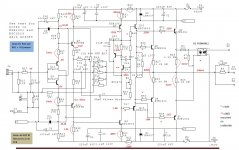
I'm a bit stumped. I have -348V offset with the trimpot as far as it will go. I have replaced all of the front end devices with closely matched units. Just replaced Q6 and Q7 with as closely matched as possible. Replaced Q20 as well. I have gone through once more and checked each resistor and am fairly sure they are all correct. I am attaching a schematic with the voltages per my amp. I tried to include all the locations you had on yours. Any help will be appreciated.
Blessings, Terry
EDIT: The schematic calls R41, R42 33R but the parts list says 0R. That is what I have if it matters.
Attachments
Last edited:
- Home
- Amplifiers
- Solid State
- SX-Amp and NX-Amp