"it is significantly different and includes a complex limiter. "
The current limiter does nothing unless you grossly overload the amplifier; like running a 2Ω load on the 4Ω tap, shutting off the PowerGuard, and driving several dB into clipping. It does nothing when driven 6dB into clipping on a properly matched load (8Ω on the 8Ω tap).
I guess my point was that you could easily change a Tiger .01 to the same output stage as the McIntosh, and we know the McIntosh works well.
The .01 is a triple with voltage gain, the Mc is a different kind of triple with voltage gain.
It looks like it would be easy to change a .01 to be the same kind of triple as the Mc.
It looks like it would be easy to change a .01 to be the same kind of triple as the Mc.
I think you'll like this
I've refined this a bit to withstand more forms of abuse. I won't bother to give a circuit description at this point, but you can overdrive it (5 Volts) into 4 Ohm loads, and there are no crazy Vbe's anywhere, and no simultaneous conduction.
However, I have faith, that someone out there can find a condition to destroy it! Of course, there's no current limiting, so driving it into a short will destroy it, but then that's always been an issue as the Tiger never had any SOA protection.
All for now...
Dan
(current values and topology assure the output transistors never saturate...that's really what's good about this version...you may quibble that I've gone a bit overboard in that respect, but that can be tweaked.)
Attachments
I'll take a look at your latest.
Edit: Your bias circuit is giving me the idea to use an Allison type of circuit.
There was a UT B version I think it was called that had SOA protection.
I think the intent what for it to be protected by the output fuse which
just might work with all the corrections and something like the big modern
MJLs with much more SOA.
I've been looking at your diode solution combined with 18 ohms from emitter
to emitter on the drivers - looks fairly good. I am aware that it might cause
some thermal issues.
Last edited:
I'll take a look at your latest.
Edit: Your bias circuit is giving me the idea to use an Allison type of circuit.
There was a UT B version I think it was called that had SOA protection.
I think the intent what for it to be protected by the output fuse which
just might work with all the corrections and something like the big modern
MJLs with much more SOA.
I've been looking at your diode solution combined with 18 ohms from emitter
to emitter on the drivers - looks fairly good. I am aware that it might cause
some thermal issues.
Hi Pete,
I'm not familiar with the Allison type circuit. Do you have any links to references on it so I can take a look?
David.
RCA 40409/40410 replace with 2N5320/5322
http://www.centralsemi.com/PDFs/products/2n5320-5323.pdf
Electronic Components & Supplies
Electronic Components & Supplies
Also look at:
2N5680/5682
MULTICOMP|2N5680|BIPOLAR TRANSISTOR, PNP, -120V | Newark.com
MULTICOMP|2N5682|BIPOLAR TRANSISTOR, NPN, 120V | Newark.com
Thanks for the info: I'll give them a try in the replacement board; looks useful in the Leach amp for the VAS stage, too.
--Damon, now busy updating a Son of Ampzilla
Hi Pete,
I'm not familiar with the Allison type circuit. Do you have any links to references on it so I can take a look?
David.
http://www.diyaudio.com/forums/soli...al-unique-allison-based-output-stages-62.html
Usually used to bias class A output stages but IIRC the Adcom 555 uses it to bias the drivers.
I've never studied it all that carefully.
Last edited:
I'll take a look at your latest.
Edit: Your bias circuit is giving me the idea to use an Allison type of circuit.
There was a UT B version I think it was called that had SOA protection.
I think the intent what for it to be protected by the output fuse which
just might work with all the corrections and something like the big modern
MJLs with much more SOA.
I've been looking at your diode solution combined with 18 ohms from emitter
to emitter on the drivers - looks fairly good. I am aware that it might cause
some thermal issues.
Hi Pete,
Which diode solution are you referring too, the diode clamp that Dan proposed or the or the diode bias scheme that I proposed. I getting a bit confused here.
David.
http://www.diyaudio.com/forums/soli...al-unique-allison-based-output-stages-62.html
Usually used to bias class A output stages but IIRC the Adcom 555 uses it to bias the drivers.
I've never studied it all that carefully.
Hi Pete,
This is quite fascinating. It will take me some time read and absorb this.
Thanks,
David.
Hi Pete,
Which diode solution are you referring too, the diode clamp that Dan proposed or the or the diode bias scheme that I proposed. I getting a bit confused here.
David.
Dan's because it is so simple. I do like yours also and don't mind a few more 5-10W resistors if needed for a new design, not sure how easy they would be to add to an old amp.
Dan's because it is so simple. I do like yours also and don't mind a few more 5-10W resistors if needed for a new design, not sure how easy they would be to add to an old amp.
Hi Pete,
Well knowing this make it easier to follow along.
David.
Thinking about the reverse Vbe problem again and I decided to try to find a solution
that does not involve clamping to correct the problem. The problem is that while a
Vbe junction is a diode in the forward direction it is a very poor diode, with very low
breakdown voltage in the other direction. This led to the idea of putting a "good"
diode in series with the base so that the combination has a high reverse breakdown
voltage. It works, the simulation is attached.
I changed the compensation to MIC just because the sim is otherwise touchy it has
nothing to do with this diode modification. I also had to adjust the output bias to
compensate for the two additional diode drops. I like this, simple and easy to do.
It also is the start for a Baker clamp on the drivers and I'll be looking into this also.
The attached .zip file has the sim and Cordell's model file, it is a newer version with a
few more models added.
Anyone have a favorite low forward drop diode with 90V or better reverse breakdown
and low capacitance to use for a Baker clamp? D2 here is the one I'm adding to fix
the reverse Vbe issue, D1 needs to have a low forward drop to work properly:
Baker clamp - Wikipedia
One concern is that with the diodes added there is no path to turn off the driver
transistors and I'm thinking of a small capacitor or bleeder resistors - thoughts?
Attachments
I have not tried the series diode mod in a real hardware but the simulation looks good.
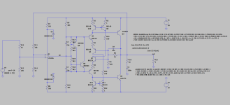
I'm calling it the Basel protection diode. It is for CFP output stages with gain similar to the Tiger topology, schematic is attached. Two diodes are all that's needed as shown below:
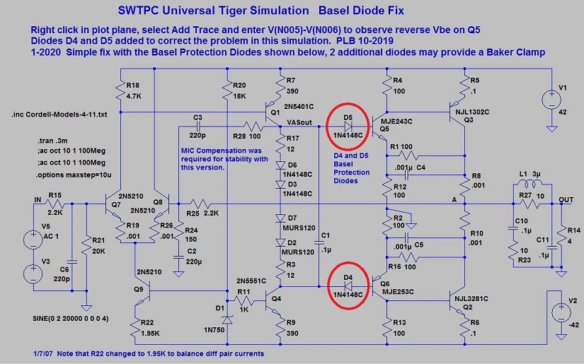
I'm calling it the Basel protection diode. It is for CFP output stages with gain similar to the Tiger topology, schematic is attached. Two diodes are all that's needed as shown below:
Attachments

I'm taking a look at this again and ran my last simulation with the diode fix to correct the
excessive reverse Vbe - that seems to work fine. That sim drives the output into clipping
and I also took a look at the current in the output devices. The cross conduction coming
out of the clipped period has a max current of 18A - could it get any worse? One advantage
of the Tigers is that they could drive the output very close to the rails, just about 2 V below.
I decided to look at the Bryston 3B that I also have posted here for ideas expecting to see
at least some cross conduction and what do you know there is none. But it only comes
within about 5 V from the rail, that's quite bad.
I believe that I used different output models for the two sims and that's something that I
should correct to see if it is a model issue helping the Bryston.
Would you please explain all the features of those diodes?
What was the primary reason for them?
What was the primary reason for them?
It's been a while since I did this. I was unhappy with the 100 Ohm feedback resistors heat, and this was one possible ~improvement. The diodes create a class-B boost to the drive current, but you may notice I changed the lower resistors to 220 so the current is about the same with only a ~1.5x gain instead of 2x. I knew I had played with this but ~lost it on another computer. I think I did more but not sure where I put it. In any case, it's not my favorite solution any more. Let me see if I can find an example of what I like better, although it's a mostly a different amplifier:
PS: and I have a couple more I could share. 1. Drop the CFP for EF and bootstrap the VAS to regain the saturation voltage. 2. Use a CFP3 to reduce the feedback heat, although stability is difficult. Interested?
PS: and I have a couple more I could share. 1. Drop the CFP for EF and bootstrap the VAS to regain the saturation voltage. 2. Use a CFP3 to reduce the feedback heat, although stability is difficult. Interested?
Attachments
Yes I'm interested in all of it but I wanted to keep this thread just for simple mods.
Please start new thread(s) with the emphasis in the title, EF, CFP3 etc. I don't like threads
that wander all over the place.
New designs are good, but what I wanted here was simple mods that could be done on an
existing UT board.
I've come to the conclusion that the Bryston output stage is the best way to have one without
cross conduction and high power in the resistors. It could be built with single polarity top and
bottom output devices if desired.
I'm interested but not sure if I'll run every simulation that you offer.
- Home
- Amplifiers
- Solid State
- SWTPC Universal Tiger Improved And Simulation