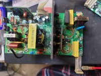
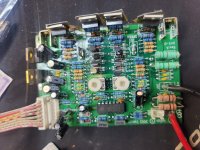
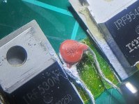
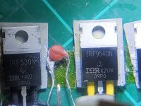
I want to share a success story!
I repaired my focal chorus sw800 sub with the help of the scematics found here
PSB SubSonic 5i problems- no go
The voltages on the manual was of great help.
D408 was dead
also R421
R 421 is under the transformer and teh new resistor was added on the underside of the pcb.
I repaired my focal chorus sw800 sub with the help of the scematics found here
PSB SubSonic 5i problems- no go
The voltages on the manual was of great help.
D408 was dead
also R421
R 421 is under the transformer and teh new resistor was added on the underside of the pcb.
The schenatics are above in this thread. These amplifiers share almost the same scematic even if the layout on the board is different.
http://remontradio.ru/wp-content/uploads/2015/07/klipsch_rw-12.pdf
PSB SubSonic 5i problems- no go
Thanks for your reply. I know Subsonic 5i and 6i almost same but as per schematic of 5i I didn't find 220uf 50v Bipolar capacitors anywhere, where 6i had them. So I am confused. What to follow or what to not.
I would also like a copy of the service diagram. Would you have one for the Bash 500S also?
Thank you
Thank you
I would also like a copy of the service diagram. Would you have one for the Bash 500S also?
Thank you
Nooby here,
I also have a Bash 500s from parts-express that needs repair &
If anyone can share the service diagram with me, I would be grateful.
I believe I've read that it this amp also uses boards made by indigo.
I look read through this thread, but have not visited all of the links in it yet.
Mods: If you can take set me free from moderated posts, I'd appreciate it.
I promise I'm a really boy (unlike Pinocchio, who only wanted to be a real boy), and that I'm also a "good boy"! You won't have any problems from me. 🙂
Hi!
Have you tested the power supply (with the power amp PCB disconnected from it)?
Perhaps I can be of help and I am not that far from you...
Cheers,
D
I just recently repaired my sub with the help of this thread and forum as well. I figured I better share my fix. My sub was dead, nothing. Turned out fuse was blown, the element was just evaporated and all black inside the tube so definitely a bad short somewhere. A fresh fuse evaporating instantly confirmed that 😜. After some troubleshooting and dead ends the problem was the irf740 FETs. One was shorted gate to source to drain but the second was seemingly ok, passed the multimeter diode test (charge the gate to turn the fet on and test short on drain source, short gate to drain and FET off with open cct source drain)
But replacing just the one caused the new fet to short out instantly and the fuse blows. At this point I ordered two more irf740 to replace both and also got a irf530 just in case as I saw other comments reporting this fet being bad in their fixes.
Replace the three FETs And fuse and voila it works!!
My board was a BASH 600123
In a Mirage Omni S10 sub
Hmm.... Seems that i have the same problem with my Mirage S10. After a lot of reading it seems the company Bash who makes these amplifier boards decided to use an adhesive on them which over many years hardened and became conductive. So i spent about an hour removing it as carefully as possible using a Dremel and a small carbide that is similar to an end-mill in design. I pulled the big caps off the board during this process and tested them, and the 1,000uf registered as 400uf and the 470uf cap measured in low as well. Not surprising considering they're made by XC and MHC.
So i just placed an order with Arrow for 2x IRF740 Mosfets, 1x Nichicon PW 1,000uf 250v cap, 1x Nichicon KW 470uf 100v cap, a few assorted resistors which i chipped with the dremel bit, 1x 10a 25c 10ohm thermistor, and 1x GBU6G-BP Bridge Rectifier. I probably don't need the rectifier or thermistor but i'd rather be safe than sorry. Grand total in parts, about $14.
The PCB is Bash 600123.
I thought i should report back in and let anyone who has run into this issue know that... IT'S ALIVE!!!!!
The Mirage Omni S10 subwoofer is back from the dead! I ended up replacing the two IRF740 mosfets, both the 1,000uf and 470uf capacitors, and the 10 ohm inrush current limiter (there was a small black mark on the original, which upon close inspection was a blow-out).
I would have replied earlier to this thread but I made a horrible mistake when removing the mosfets. Being the total hack that I am when it comes to this kind of stuff (100% poorly self-taught), i managed to tear out the via/eyelets and had to repair them.
So to anyone with one of these subs that instantly blows its fuse when connected to power, you'll likely be able to fix it by replacing the two mosfets, inrush current limiter, and the fuse. Considering how old these subs are, might be good to replace the caps as well. I plan on replacing the rest of the smaller caps soon.
Please, I've a Focal with Indigo Canada 600109 PSU, a defective power supply. Could you send me a copy of the service manual or schematics ? Many thanks!
edest@libero.it
edest@libero.it
I know this is a pretty long shot. I have a busted thermistor RT1 on the same Omni S10 and letters cannot be read.I just recently repaired my sub with the help of this thread and forum as well. I figured I better share my fix. My sub was dead, nothing. Turned out fuse was blown, the element was just evaporated and all black inside the tube so definitely a bad short somewhere. A fresh fuse evaporating instantly confirmed that 😜. After some troubleshooting and dead ends the problem was the irf740 FETs. One was shorted gate to source to drain but the second was seemingly ok, passed the multimeter diode test (charge the gate to turn the fet on and test short on drain source, short gate to drain and FET off with open cct source drain)
But replacing just the one caused the new fet to short out instantly and the fuse blows. At this point I ordered two more irf740 to replace both and also got a irf530 just in case as I saw other comments reporting this fet being bad in their fixes.
Replace the three FETs And fuse and voila it works!!
My board was a BASH 600123
In a Mirage Omni S10 sub
Would you be so kind to tell me the part number? It is located on the Audio Amp board, not the power supply board. It's in between the 4 mosfets.
That is if you can. 🙂
Attachments
Started Googling a board assembly and as brought to this thread. Seems to be a mix of old and newer posts.
Just picked up an Axiom Subwoofer. Was stated to be DOA. Cabinet in very nice condition, Woofer checks out a good. Using a spare plate amp the woofer did it's thing.
The guts of this are a board made by INDIGO ( which is what I went hunting for information on). The stenciling on the PCB reads
"INDIGO MAIN 600049" and "REV7"
I asked the fellow I got the sub from about any history as it looked tampered with. He explained he sent it to a guy to have a look at for potential repair, and the guy couldn't figure it out. In the certer of this PCB are pair of transistor type devices and a 100uf cap. The cap looks sketchy and one of the leads snapped off when I was assessing the soldering. Further inspection of the underside of the PCB shows some horrific attempt as reflowing the solder on the transistors and some heavy blackening of the area associated with the 2 transistors and cap. I've ordered replacement components for those and some others - refreshing all the caps while I've got it apart, and the 2 power devices on the edge of the PCB. I don't know what if anything was repaired, and I am beginning to wonder whether a substitution was done on those two transistors. hunting for a schematic to identify those, if possible.
Thanks
Upon looking to diagnose the problem on my HSU Research STF-2, I stumbled on this page. Oddly enough, the SFT-2 appears to use the same layout as most subs. So far changed out MOSFET IRF530N , IRF9450N, IRF740, replace cap 1000uf 200v & the pair of 220uf 250v. Before all the other MOSFET replacements, I changed out the main caps and adjusted the potentiometer, and got it working, but noticed it running real hot. Dialed back the adjustments and lil more and ran it for a few mins and everything went dead. I changed out the fuse and they kept popping. Finally, I've gone ahead and swapped out all the MOSFET and replaced the pair of 220uf 250v (old use stock). I can't get sound from the source to speakers or subs but do notice a loud fluttering and an obvious short indicated on my dim bulb tester. Kind of stumped on where to proceed next on troubleshooting and finding the short. Any help is appreciated. Thanks


Not sure if still needed, but here are the photos for them.I know this is a pretty long shot. I have a busted thermistor RT1 on the same Omni S10 and letters cannot be read.
Would you be so kind to tell me the part number? It is located on the Audio Amp board, not the power supply board. It's in between the 4 mosfets.
That is if you can. 🙂


I thought i should report back in and let anyone who has run into this issue know that... IT'S ALIVE!!!!!
Aaaaaannnnddd..... It's dead again. Gonna replace those mosfets and the inrush limiter. And a couple resisters.
edit\ nevermind, the sub still works fine. Its odd that it wasn't working on my Harman Kardon AVR354 receiver, so i tried it on my Harman Kardon AVR2700 and it wasn't working on that either. But this morning i hooked up my iphone using a lightning to 3.5mm jack and a 3.5 male to stereo RCA plugs which i plugged into the sub and it worked! Sooo... i doubt the sub out on both receivers are borked (yes, i enabled the sub) so the only thing left would be the cable. And considering the fact that i have a 9 month old puppy rampaging around the house, i think we might have the culprit.
I have this same amp in my 2 old Nuance towers, both started to fail, i have the same hot burnt area around the transistors and resistors slightly off center of the power caps. the 3 resistors on mine are badly discolored and cant make out the values very well, i've replaced the main caps, and they worked fine for a while then started making a humming sound that just kept getting louder. been trying to figure out the issue since. you have any luck?Started Googling a board assembly and as brought to this thread. Seems to be a mix of old and newer posts.
Just picked up an Axiom Subwoofer. Was stated to be DOA. Cabinet in very nice condition, Woofer checks out a good. Using a spare plate amp the woofer did it's thing.
The guts of this are a board made by INDIGO ( which is what I went hunting for information on). The stenciling on the PCB reads
"INDIGO MAIN 600049" and "REV7"
I asked the fellow I got the sub from about any history as it looked tampered with. He explained he sent it to a guy to have a look at for potential repair, and the guy couldn't figure it out. In the certer of this PCB are pair of transistor type devices and a 100uf cap. The cap looks sketchy and one of the leads snapped off when I was assessing the soldering. Further inspection of the underside of the PCB shows some horrific attempt as reflowing the solder on the transistors and some heavy blackening of the area associated with the 2 transistors and cap. I've ordered replacement components for those and some others - refreshing all the caps while I've got it apart, and the 2 power devices on the edge of the PCB. I don't know what if anything was repaired, and I am beginning to wonder whether a substitution was done on those two transistors. hunting for a schematic to identify those, if possible.
Thanks
- Home
- Loudspeakers
- Subwoofers
- SVS sub Indigo board repair
