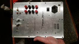
Focal Chorus 700sw
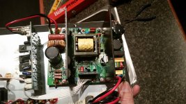
Thanks for the schematic!! I had visible burn marks on my power supply around one corner of the 16 tap transformer. After cleaning things up and repairing traces my plate amp powers up, green led, but no sound at all. There are a couple of transistors on the amp board that are warm to the touch so some sort of power is making it to that board. can anyone help? Its been years since my electronic days in college :/
Thanks for the schematic!! I had visible burn marks on my power supply around one corner of the 16 tap transformer. After cleaning things up and repairing traces my plate amp powers up, green led, but no sound at all. There are a couple of transistors on the amp board that are warm to the touch so some sort of power is making it to that board. can anyone help? Its been years since my electronic days in college :/
Just interested has anyone tried to contact the SVS for repair? I realized that the power supply modules are the same the Tannoy and SVS, the photos.
Thanks for the schematic!! I had visible burn marks on my power supply around one corner of the 16 tap transformer. After cleaning things up and repairing traces my plate amp powers up, green led, but no sound at all. There are a couple of transistors on the amp board that are warm to the touch so some sort of power is making it to that board. can anyone help? Its been years since my electronic days in college :/
regnadanger
Have you changed the capacitors around the voltage regulators?
How about the voltage regulators themselves?
I advise changing them all - better using 105C rated caps...
(Pictures of your board(s) would help those that can help you...)
D
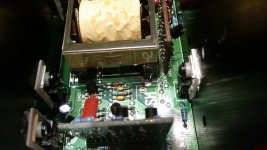
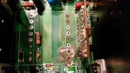
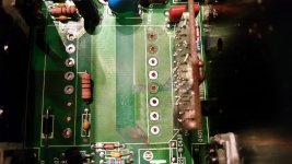
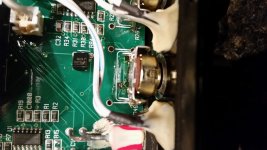
Heres some pics. i took some of the board with xformer removed so i knew which taps i needed to check continuity on after soldering to make sure the opposite side made contact. the chip appears to have been ground down to remove id info. I wiped it down a bit but didnt really help. please look at the pic of the board with xformer removed. I digitally rebuilt the trace that was burnt. can someone verify the accuracy?
Attachments
regnadanger
Have you changed the capacitors around the voltage regulators?
How about the voltage regulators themselves?
I advise changing them all - better using 105C rated caps...
(Pictures of your board(s) would help those that can help you...)
D
no, i would need assistance iding them. Can they be checked first?
Heres some pics. i took some of the board with xformer removed so i knew which taps i needed to check continuity on after soldering to make sure the opposite side made contact. the chip appears to have been ground down to remove id info. I wiped it down a bit but didnt really help. please look at the pic of the board with xformer removed. I digitally rebuilt the trace that was burnt. can someone verify the accuracy?
You can re-photograph this item?
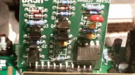
???????-????: ???????? - BASH Indigo 660037
You can re-photograph this item?
???????-????: ???????? - BASH Indigo 660037
Sure ill retake and try to get in closer
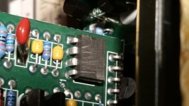
This is the best u can do with my cellphone. The surface of the ic chip has been filed away. Are you trying to determine the part number of the chip? Do you think it has failed?
Thank you, I have a chip too worn sandpaper as you.
This is the best u can do with my cellphone. The surface of the ic chip has been filed away. Are you trying to determine the part number of the chip? Do you think it has failed?
Thanks for the photo. In addition to this chip all other parts can be bought without problems.
ok, is this chip my problem though?
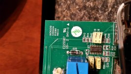
Also, I have picked up a Niles SW300 sub with a BASH amp in it. Its not the same amp though. Appears to work but two of the pots have been replaced with cheap pots. I also question weather or not the values are correct. R29 and R49 have been replaced with 10k audio taper pots. I feel like I should be getting more volume and thinking maybe the pots are the wrong value? Unless zero ohms is max volume, then it wouldn't matter as far as max volume goes. the board is "Indigo 610064"
Also, I have picked up a Niles SW300 sub with a BASH amp in it. Its not the same amp though. Appears to work but two of the pots have been replaced with cheap pots. I also question weather or not the values are correct. R29 and R49 have been replaced with 10k audio taper pots. I feel like I should be getting more volume and thinking maybe the pots are the wrong value? Unless zero ohms is max volume, then it wouldn't matter as far as max volume goes. the board is "Indigo 610064"
Attachments
This is the best u can do with my cellphone. The surface of the ic chip has been filed away. Are you trying to determine the part number of the chip? Do you think it has failed?
I think this may help...
Indigo HC1010 and HC1011 B.A.S.H. Modules
I fixed lots of Bash amps before, but I have not seen a failure like your (i.e. damage around the EDT core).
🙁
I was thinking the glue caused the arcing. But after cleaning things up and reinstalling xformer all I have is a green led. Granted I have not measured any voltages yet leaving main power supply board yet, it seemed like this ic chip picture request was going somewhere so I didn't start measuring anything...
I was thinking the glue caused the arcing. But after cleaning things up and reinstalling xformer all I have is a green led. Granted I have not measured any voltages yet leaving main power supply board yet, it seemed like this ic chip picture request was going somewhere so I didn't start measuring anything...
Just try this easy test...
(1) Unplug the amp from the AC outlet.
(2) Leave all interconnecting flat cables in place.
(3) Disconnect the speaker wires.
(4) Disconnect the red and black wires between the power supply and the output board (unplug at the output board side).
(5) Make sure you have no tools, extra wires, pint of beer, etc., that can cause a short.
(6) Make sure the fuse is intact and of the correct value.
(7) Connect your voltage meter (DC) to the wires from item (4) above.
(8) Plug the amp to AC and turn it ON
(9) Measure the power supply DC voltage - it should read between 8 and 10 Volts
If it measures OK, then I would not worry (in principle) about the two daughter boards in the power supply. Chances are that your output transistors and/or voltage regulators need be replaced.
Just a suggestion... 😀


Changed one irf540 and two irf740 transistor , and one DB-6 Diac Trigger Diodes, which now can neither find where to buy (((
Send someone to Russia I two DB-6 Diac Trigger Diodes in the envelope )))
Send someone to Russia I two DB-6 Diac Trigger Diodes in the envelope )))
- Home
- Loudspeakers
- Subwoofers
- SVS sub Indigo board repair