The core is saturating even with that large inductance ... it's a power transformer after all . You would need more turns for that core . But many many amplifiers don't produce full power at 20Hz , neither comercial audio transformers 😀 For audio transformers there is an economical compromise because you would need very big cores for full power at 20Hz vs 1KHz.
Many people don't even measure , just build .
Many people don't even measure , just build .
Last edited:
Depanatoru,
Correct, more turns = more inductance.
But . . .
More turns at the same DC current = More Amp x Turns, and . . .
More Amp x Turns, means even earlier core saturation.
And, more Amp x Turns of low frequency AC also means earlier core saturation.
And, the Un-balanced push pull plate current acts exactly the same as a DC current of a single ended output stage (that is why most people do not use a Push Pull output transformer with a single ended output stage).
And it is a real good reason to be sure to balance the plate currents of a push pull output stage.
The ones who use push pull output transformers with single ended stage use a coupling cap from the output plate, to the push pull primary (and usually a choke load on the plate).
That is called a Parafeed output stage.
Prevent early coren saturation, Increase the amount of core material.
There is no fooling mother nature (or no fooling physics, this side of the un-proven unified field theory).
Just my opinions.
Last edited:
The transformers are what they are, useless for a high power fullrange amp but, unless I'm missing something, fairly adequate for a class A amp with two large sweep tubes per channel.
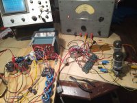
Right now I'm seeing ~30W with 320V B+ and 340R + 220uF in each cathode "leg". At 285V 95mA per tube you can feel the heat radiation from two feet away 😀
Right now I'm seeing ~30W with 320V B+ and 340R + 220uF in each cathode "leg". At 285V 95mA per tube you can feel the heat radiation from two feet away 😀
We are talking about AC saturation ... more inductance less current , less flux .
Of course a bigger core has more inductance with the same number of turns , or you have more space for more turns .
This is obvious if you compare a classic E+I power transformer ( low inductance low number of turns ) with an audio transformer the same size and see on the scope the low frequency response .
Last edited:
Depanatoru,
So Low Frequency AC saturation is not dependent on Amp x Turns???
A given power has to have a given amount of amps at the primary impedance, because the load requires a stepped-up number of amps at the secondary impedance, in order to have constant power, regardless of the frequency.
Yes? No?
I understand that the total number of amps is dependent on the load that reflects to the primary, in parallel with the primary inductive reactance versus frequency.
But doesn't adding turns become a loosing battle?
Please help me understand.
Thanks!
I suppose I missed the point.
But if I increase the primary turns, I have to increase the secondary turns by the same percentage ratio; in order to keep the input and output impedance the same.
And, then I have to use smaller wire diameter to be able to fit more turns in the core, and increase the primary DCR and secondary DCR; that increases the insertion losses at all frequencies, including the midrange.
Or, as I said, increase the amount of laminations, and start the transformer design from scratch. And a larger core means more wire length, so need larger wire to keep the DCR a fixed percentage of the target impedance.
No free lunch for me.
Last edited:
Maybe hard to understand , the core saturating current is not the usefull current that passes from primary to secondary , but the idle no load current that stays in the core. This is not depending on the secondary load , so if a transformer is not saturating with no load it will be good at any load .
For a power transformer it is easy to measure this current at mains voltage/frequency ... with a meter. Thats why a power transformer must have a minimum number of turns for a core section ( usually you don't know the material maximum working flux ) , frequency and working voltage . In fact a minimum inductance . Below the threshold would just burn .
Like this, in an amp some current will just flow in the primary and couse saturation , obviously then you turn the volume up you have more voltage across the primary , more idle current ... I = V/Z The impedance is mostly the inductive reactance so it gets lower and lower as frequency goes down ... you will see saturation first at 20Hz .
Increase the primary inductance by adding more turns or using bigger core and you can get more power at low frequency without saturation .
The DC is adding to AC flux in single ended transformers , they saturate faster . In push-pull of course in theory the DC effect is cancelled
Last edited:

OK.
1. Power transformer used as an output transformer:
So, for a given a particular power transformer (EI interleaved, or Toroid) that is re-deployed as a push pull output transformer . . .
The AC saturation versus frequency is fixed by that particular model's characteristics, and the primary inductance is a major factor.
And . . . the Un-balanced Push and Pull DC currents will take away some of that capability the transformer had in terms of AC current versus frequency versus core saturation (versus perfectly matched quiescent DC currents).
2. Power transformer used as a power transformer:
Perhaps the lack of turns, lack of core, or both, is the reason why my Dyna Stereo 70 power transformer runs very hot (when used as a power transformer).
I use it in my totally modified Dyna ST70 amplifier that uses lower total filament currents, lower B+ current, and choke input instead of cap input B+ filter (Now, the loading of the transformer is much easier than it used to be in the original ST70 circuit).
. . . Still runs Hot!
Last edited:
I have several transformers that run at over 50°C with no load at all. Some transformers are just cheap 🙂
It depends on your POV: voltage or current.Depanatoru,
Correct, more turns = more inductance.
But . . .
More turns at the same DC current = More Amp x Turns, and . . .
More Amp x Turns, means even earlier core saturation.
And, more Amp x Turns of low frequency AC also means earlier core saturation.
In general, for a PT, you use voltage and don't care about current or inductance (they self-adjust).
The formula is n=V/(4.44*Bmax*F*Ae)
For an inductor (and related devices like the OP transformer of a SE stage),
the formula is n=LI/(Bmax*Ae)
This always applies to the winding you study: magnetizing current for a primary for example.
The current drawn from outside the tranformer, like secondary current never intervene in the calculations
OK.
1. Power transformer used as an output transformer:
So, for a given a particular power transformer (EI interleaved, or Toroid) that is re-deployed as a push pull output transformer . . .
The AC saturation versus frequency is fixed by that particular model's characteristics, and the primary inductance is a major factor.
And . . . the Un-balanced Push and Pull DC currents will take away some of that capability the transformer had in terms of AC current versus frequency versus core saturation (versus perfectly matched quiescent DC currents).
2. Power transformer used as a power transformer:
Perhaps the lack of turns, lack of core, or both, is the reason why my Dyna Stereo 70 power transformer runs very hot (when used as a power transformer).
I use it in my totally modified Dyna ST70 amplifier that uses lower total filament currents, lower B+ current, and choke input instead of cap input B+ filter (Now, the loading of the transformer is much easier than it used to be in the original ST70 circuit).
. . . Still runs Hot!
If a transformer is running hot doesn't mean it is saturating . It is just made "economical" with fewer turns , but not below minimum . Or the wires in primary and secondary are thinner that it should be .
Lets say you have a beautifull monophase 110 or 220V transformer that is dead cold with no load . Put it betwwen 2 phases , you could think that the power dissipated would be about 4X higher and still it would run just a little warm 😀 But it will saturate and burn easily .
Like this , if you use a power transformer as output transformer , at a certain output power the voltage across primary will become greater than 110/220V rating and if you test it at 20Hz the situation is much worse . At some point it would saturate but not burn because the tube has high internal resistance 😛 . Using transistors they would short .
Last edited:
Transformers that were knitted next to the edge may also run hot without load, due to the missing voltage drop within the primary winding.
Best regards!
Best regards!
+1 What members Elvee and Depanatoru claim.
For AC signal, flux density is independent of current. A transformer VA rating is entirely dependent of permissible dissipated heat and voltage sag. You can run a 100VA transformer rated at 500VA for a short time, the core will not saturate, but it will likely overheat if you do not increase cooling. In fact the core will work at a slightly lesser flux density due to sagging.
When designing power transformers, there is a balance between flux density and VA. The highest optimal flux density translates into a lower amount of turns, hence higher VA rating due to lower Rdc losses. But increasing flux density above a point translates into heat losses due to core saturation, resulting into permeability drop in the end giving an inductance drop and resulting into Rdc losses again, due to lower primary inductive reactance.
Bac = Vrms / 4.44 x f x Afe x n ; 4.44 is the sinewave shape factor
From a DC point of view, the core saturates with increasing DC current. There is a feedback mechanism though. The more the saturation, the more the permeability drops, hence the more DC flux density is reduced. This is why, when a core inductor gets into saturation, the slope is somewhat linear, until Rdc starts taking over.
If you increase turns, of course you must cut back permeability, most practically by introducing an air gap, in order to keep inductance controlled.
Bdc = L x Idc / n x Afe
Last edited:
Like this , if you use a power transformer as output transformer , at a certain output power the voltage across primary will become greater than 110/220V rating and if you test it at 20Hz the situation is much worse . At some point it would saturate but not burn because the tube has high internal resistance 😛 . Using transistors they would short .
A standard 120/240 trafo will run at its DESIGN flux density when you apply 170 volts peak across half the secondary, at 50 Hz. They can all be safely used this way, and most will have relatively low distortion. Push the voltage higher or frequency lower and you run closer to saturation - distortion and increased current draw is the result. The flatter the top of that BH curve, the quicker the onset. Transformers designed to run hot and save weight/money will bite up you in the butt before one that runs cool. But don’t expect miracles either way. 200 volts on a 120V winding (at 50Hz) will make even the most expensive power transformers angry. For small low budget projects where you may be using an isolation trafo to provide a 170 V B+ to run a pair of $3 tubes, that is really all you need. Peaks wouldn’t be much more than 140V, getting you to the magic 41.5 Hz. For a guitar amp double that is all you care about, so you could run a 300 volts supply.
When you interleave two, you have a 480 volt primary (and two secondary voltage options, series and parallel). You can apply up to 340 volts at 50 Hz, or 170 down to 25 and run at the design flux density. Or anywhere in between - it just scales linearly. This puts it in practical operating range for amps over 10 watts, even with common tubes.
Next up is to replace those whimpy 6L6s with something more...knuckle-dragging, and rewire the transformers to ~2k/8R and see what happens.
Attachments
Although I fully second wg-ski's arguments in #53, I'd really being itched to try something like this for myself and see/measure what happens. Just have to find a suitable transformer, as 115 + 115 Vac ones are rather scarce here in Germany. Cathode NFB surely will significantly reduce distortion and the final pair's output impecance the transformer looks into, but we can't completely disregard nature's laws.
Btw, I've calculated your primary impedance at [(115 + 18) x 2]² x 8 ~7 k.
Best regards!
Btw, I've calculated your primary impedance at [(115 + 18) x 2]² x 8 ~7 k.
Best regards!
The 115+115 primary are the ones we find all over the place here, especially the low budget options. Having 2x18 AND 2x9 secondaries (as long as both are for a decent current) is a real find - as you’ve got LOTS of impedance options, although some are going to be pretty low. If you had two identical you’d be in hog heaven for experimenting.
Let´s see what we have here: With 230V 50Hz across both 115V windings I get 20,2V on the 18V windings and 10,2V at the 9V windings, unloaded. The highest possible turns ratio would then be (115+115+20,2+20,2)/10,2 = 26,5:1, or ~5,6k:8R.
5,6k a-a is a suitable plate load for a lot of different tubes, although the ~5W power rating at low frequencies points in the direction towards triode connection and class A operation for quality rather than quantity.
The next option is to connect the two 9V (10,2 unloaded) in series and get 13,25:1 or ~1,4k:8R, an interesting plate load for bigger sweep tubes running "low and hot" in class A. This connection should be good for about 20W at 30Hz if my clalculations are correct.
We could also connect all the secondaries in series as one 27-9-0-9-27V winding , ground the 0V point, connect the 27V points to cathodes and the speaker across the two 9V windings. This would result in a 14,25:1 ratio or 1,6k:8 and give us some extra CFB voltage as a bonus.
Another option is using two toroids in a Norman Crowhurst "Twin Coupled" arrangement. Twice the primary voltage effectively, twice the power, and 50%
CFB. You do need to figure for 16 Ohm outputs on each xfmr so as to get 8 Ohms in parallel ( with 1.414.x the secondary voltage for twice the power output ).
CFB. You do need to figure for 16 Ohm outputs on each xfmr so as to get 8 Ohms in parallel ( with 1.414.x the secondary voltage for twice the power output ).
The Crowhurst "Twin Coupled" amp would be an interesting option but I only have two transformers. The German Ebay seller had three, which confirms the universal formula X=N-1 where X is the number of of a specific vintage/surplus/custom made component you need for a project and N is the number of said components available... 🙂 Though, I think I could get two more of those massive toroids from the start of this thread. That would make an interesting contrast to my usual 3W SE amps for sure.
You don't get more power at low frequency whatever combinations you do with the secondaries ... this is related to primary inductance and core saturation .Let´s see what we have here: With 230V 50Hz across both 115V windings I get 20,2V on the 18V windings and 10,2V at the 9V windings, unloaded. The highest possible turns ratio would then be (115+115+20,2+20,2)/10,2 = 26,5:1, or ~5,6k:8R.
5,6k a-a is a suitable plate load for a lot of different tubes, although the ~5W power rating at low frequencies points in the direction towards triode connection and class A operation for quality rather than quantity.
The next option is to connect the two 9V (10,2 unloaded) in series and get 13,25:1 or ~1,4k:8R, an interesting plate load for bigger sweep tubes running "low and hot" in class A. This connection should be good for about 20W at 30Hz if my clalculations are correct.
We could also connect all the secondaries in series as one 27-9-0-9-27V winding , ground the 0V point, connect the 27V points to cathodes and the speaker across the two 9V windings. This would result in a 14,25:1 ratio or 1,6k:8 and give us some extra CFB voltage as a bonus.
Of course if you tested good and 5W is the real limit .
I would use them with EL84 class tubes , even EL84 itself would work fairly ok at 5K6
- Home
- Amplifiers
- Tubes / Valves
- Surplus toroid transformers as OPTs...with a little twist.