Arjen's board
I have recently replaced every single SMDs on one of the boards with discrete components and I must say I am truly impressed by its effects. My T-amp sounds so transparent and resembles a valve/tube amplifier not only in its overall smoothness, warmth and micro dynamics but also with higher resolution, its timing gotten right, lots of rhythmic bounce and sufficient bass and bass weight we could possibly seek from an amplifier.
Read more about it at the newly updated page of my blog: T-amp
I hope this is the right place to put this question:
I have two of these amps bi-amping speakers with a little "sub"connected to the signal inputs.They are powered by a double insulated 3W laptop power supply at 16V (never had any trouble).The "sub" has its own 230V earthed power.
With a desktop computer,with earthed power supply,there's no problem.With my netbook (Ausus 1000H) there's a groundloop 50Hz hum.
It does not matter whether the netbook is on its double insulated power brick or battery.
When I start some music there's a sharp little crack and the music plays great and the hum disappears.
When the music is turned off,6 or 7 secs later it reappears.
I know this has got to be a capacitor but where and is there anything I can do about it. It's the same without the sub.
I wondered if it's capacitance in the amp power supply, with it being able to earth when connected to the desktop,but unable when connected to the netbook,but why does it disappear when Winamp is playing?
It has me intrigued.
thanks
Paul
coit said:
With a desktop computer,with earthed power supply,there's no problem.With my netbook (Ausus 1000H) there's a groundloop 50Hz hum.
It does not matter whether the netbook is on its double insulated power brick or battery.
When I start some music there's a sharp little crack and the music plays great and the hum disappears.
When the music is turned off,6 or 7 secs later it reappears.
I would say this sounds like a problem with the laptop sound card, not a ground loop. The fact that it makes no difference whether the laptop is powered by battery or mains shows it can't be a ground loop, especially as the earthed desktop computer doesn't show the problem. The fact that the hum only reappears after 6-7 seconds may indicate the soundcard goes in to some kind of sleep mode which emits the hum. Maybe try an external usb card instead?
---Sure electronics board---
First I must say thank you all for so much great informations about mods over t-amp. It's a real pleasure to see all that ideas and enthusiasm over something.
Many days has past from first modification of sure board,and some things become a standard in the way to good sound.
But some other things are still in the little mess,like capacitivity of rails capacitors( this vary from nothing to solder,over 2000uf,to insane 20000uF ) Yes,I understand,that was experimental period.
In this days,what is your opinion ,how much uF is optimal?
Second, is it better to put Oscon near the chip,or same tipe as on rails? Of course,capativity will be in the range of 470uF...
Third, caps to put before DC input,some says <500uF ,but others can swear that no low frequncy will show if =>4000uF is present...
I would really be happy if someone find a little time to write some comment over this ,especially those who experiment with sure boards and achieve good results in overall sound.
Thank you very much in advance!
Best regards,
Woody
First I must say thank you all for so much great informations about mods over t-amp. It's a real pleasure to see all that ideas and enthusiasm over something.
Many days has past from first modification of sure board,and some things become a standard in the way to good sound.
But some other things are still in the little mess,like capacitivity of rails capacitors( this vary from nothing to solder,over 2000uf,to insane 20000uF
) Yes,I understand,that was experimental period.In this days,what is your opinion ,how much uF is optimal?
Second, is it better to put Oscon near the chip,or same tipe as on rails? Of course,capativity will be in the range of 470uF...
Third, caps to put before DC input,some says <500uF ,but others can swear that no low frequncy will show if =>4000uF is present...
I would really be happy if someone find a little time to write some comment over this ,especially those who experiment with sure boards and achieve good results in overall sound.
Thank you very much in advance!
Best regards,
Woody
Hi Woody,
I think "justblair" would be best to answer this, he is putting a lot of work into getting the best out of these boards (and has a most excellent web site).
I can only tell you what I ended up with.😉
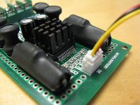
All the power caps are removed and replaced with Pany FC's, 1000uF on each rail and 2x180uF at chip.
Input caps are 1.5uF, no shortage of bass to me. DC offset reduced to near zero by trimmers and output inductors replaced by homemade 15uF torroid inductors. Each power rail has a direct power supply bypassing the diode.
Power supply is switch mode, set at 13.5V ...
I doubt if the same thing works for everyone.😀
Regards Barry..
I think "justblair" would be best to answer this, he is putting a lot of work into getting the best out of these boards (and has a most excellent web site).
I can only tell you what I ended up with.😉
All the power caps are removed and replaced with Pany FC's, 1000uF on each rail and 2x180uF at chip.
Input caps are 1.5uF, no shortage of bass to me. DC offset reduced to near zero by trimmers and output inductors replaced by homemade 15uF torroid inductors. Each power rail has a direct power supply bypassing the diode.
Power supply is switch mode, set at 13.5V ...
I doubt if the same thing works for everyone.😀
Regards Barry..
Attachments

Thank you very much for response 🙂
Did you attach rail capacitor just at one point where was C29,or you pass the line to C31?
Don't have the schematic so I don't know how to act when remove those six 100uF caps.
Can you put some details on that inductors,recomendations for replacement?
Did you attach rail capacitor just at one point where was C29,or you pass the line to C31?
Don't have the schematic so I don't know how to act when remove those six 100uF caps.
Can you put some details on that inductors,recomendations for replacement?
Hi Woody,
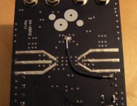
Rail caps are attatched at one point only, C29 & C26 for other rail.
I have done the power supply different now, I removed D1, and used a single wire from Vdd to the centre point between rail caps.
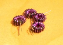
Like I said I wound my own inductors, but I can't remember what torroids I used?
Rail caps are attatched at one point only, C29 & C26 for other rail.
I have done the power supply different now, I removed D1, and used a single wire from Vdd to the centre point between rail caps.
Like I said I wound my own inductors, but I can't remember what torroids I used?
Attachments
audio1st said:
Could you please tell us what wire did you use, diameter etc...
Regards Aleš
woody_allen said:---Sure electronics board---
But some other things are still in the little mess,like capacitivity of rails capacitors( this vary from nothing to solder,over 2000uf,to insane 20000uF
In this days,what is your opinion ,how much uF is optimal?
I cannot say for sure on what is the optimal uf for the boards, I tried no additional caps versus 1500 extra versus 3000uf extra (per rail)
In my setup, additional capacitance made only minor improvements to the bottom end of the sound. I would stress that my power supply is a rated at 29A into 12v. Possibly with lesser powered supplies, rail capacitance will be more improtant.
What I would say is that if you are using 470uf caps, you may get different results.
woody_allen said:Second, is it better to put Oscon near the chip,or same tipe as on rails? Of course,capativity will be in the range of 470uF... [/B]
Logic would say near the rails, though you might find that space is at a premium on the board near the rails. On my website you can see that I placed two of the caps on the ceramic caps close to the chips input. But to get the connection there I had to use a long lead from the cap.
One thing I would point out here, the route from the cap bank on the sure boards to the input of the chip is convuluted. From the cap bank, the rail goes down to the underside of the board through vias, it the travels to the middle of the underside(where left and right channels power rails are joined), then up to the top, then meets the smaller power reseviour caps, then finally enters the chips. If you attach your resevoir caps to the small caps near the rails, you will have a theoretically better connection point.
On a related note, I would look closely at how to improve this convoluted power rail path through the board. Albin earlier in this thread pointed out that he had heard some improvements when he had separated the power rails for the left and right channels. I tried this, and found the difference to be more profound than capacitance changes.
seperating power rails
I went a step further than albin with my separation of the rails, splitting them back at the power supply rather than on the boards inputs.
woody_allen [/i] Third said:Hi Woody,
I think "justblair" would be best to answer this, he is putting a lot of work into getting the best out of these boards (and has a most excellent web site).
I can only tell you what I ended up with.😉
Barry, I am suprised at this comment, You have pioneered with these boards, and deserve maximum credit for both publicising your efforts and supporting those seeking to understand them. My site reflects more other peoples suggestions for this board that I have tried, and my take on how to perform them. I have hopefully credited people correctly for their inputs 🙂
PS I would also recommend the higher rail voltage, sounds better to my ears.
@justblair
Thank you very much!
However,did you suggest to remove C10 and C18 and put better caps there instead of bypass C9 and C19 ? Well,logic tells us that would be better solution because of shorter signal line...
And inductors... many people says that is very sonicly upgrade to replace stock inductor for air core ones,and what I can see,only audio1st has do such a upgrade ( not air core,but upgrade ).
Once again I must congratulation audio1st ,you and many others to share the expirience with mods of t-amp with all of us ,and to have patience for answers so many questions 🙂
Here a foto from my current work in progress:
Two sureelectronics boards, driven by a Rod Elliott active crossover.
The torroid tranny for the LM350 psu to run the t-amps. And the R-core tranny for the crossover.
This will be a three channel amp, to drive my speakers as active speakers (of course, I make two of this 3-channel amps).
Franz
An externally hosted image should be here but it was not working when we last tested it.
Two sureelectronics boards, driven by a Rod Elliott active crossover.
The torroid tranny for the LM350 psu to run the t-amps. And the R-core tranny for the crossover.
This will be a three channel amp, to drive my speakers as active speakers (of course, I make two of this 3-channel amps).
An externally hosted image should be here but it was not working when we last tested it.
Franz
Fransz active 3way
Hi Franz,
This exactly what I am after in a 2 way version.
Need to populate my filters and order 2 boards.
Looks very nice!!
Peter
Hi Franz,
This exactly what I am after in a 2 way version.
Need to populate my filters and order 2 boards.
Looks very nice!!
Peter
Hi Henk
I already use my speaker in quite a comparable configuration: a active crossover from Monacor, driving sureelectronics board just flying around...
With this configuration I could figure out the crossover frequencies. But I dont like the Monacor xover: many electrolytics in the signal path, many many opamps.
Even when I like to build tube amps: this kind of t-amps in active configuration gives you very good control over the speakers. And a comparable solution with tubes would be heavy and quite expensive!
Franz
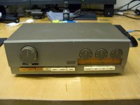
I found a small power supply in a drawer today. Only 1.2A but smaller as my big test power supply. Took the broken T-amp and my multimeter from the shelf again. Pulled my “I know the world of electronics face” and started checking the board again. After a check I still had no clue why the amp was not working and got back to work. I don’t know why but I just had to try the small power supply. I took the board from the shelf with some speakers and mounted all wires again. Great news this time a bad scratchy, scraping sound came from the speakers this time. I muted iTunes (happy it worked and still a bit disappointed because of the bad sound) but I could not resist to try it once more and in the next 30 seconds the sound became better and better. It’s running with a loud and clear sound on some old small 4Ohm Jamo’s now. Can’t wait to test them on some bigger speakers. I made a small heatsink from a bigger one which came from an old Nvidia grapics card. I think I will search the attic for some other parts I can recycle for my T-amp this weekend. Have a great night (or day),Aad
Attachments
There is definitely something wrong with this board. Last time it worked fine. After a few hours the sound became better and better. I thought to give another go today. But it’s again as dead as a doornail. Strange as it worked fine last time. I think I’ll have to start a new project. Don’t know if I order a new one or I will go for a upgrade and order an Amp6 at 41Hz. I don’t have to hurry, it won’t be here before Christmas anyway. Plenty time now for finishing my speakers the comming vacation days.
- Status
- Not open for further replies.
- Home
- Amplifiers
- Class D
- Sure Electronics Tripath boards?