Peter Menting, ZL2BPS: that's the sheet I referred to.
Page 11 has a recommendation on how to trim the output voltage. It works as descibed there. If you want more precision in the trimming (and less hassle fiddling with the trim pot) you can add 20k resistors to either side of the pot.
I did that with the sure board where I re-used the 20k SMD that came on the board.
If anyone is interested I can post a recipe listing the sites on the boards I soldered the parts to.
Re: Inductors
Hey, thanks.
I have been to the SZ market, there are many, but there is no way I can tell if the inductors are good for t-amp output.
I have search this forum and it seems the MPP type is good.
Size between 12~20mm dia will fit.
I suspect a few of the diyer here will be interested in a high quality inductor too for the t-amp.
ArjenShenzhen said:There must be, i see them every day here.
ill put a movie of the market on youtube when i have the time.
tell me what value you are looking for and ill let you know what i can do.
Hey, thanks.
I have been to the SZ market, there are many, but there is no way I can tell if the inductors are good for t-amp output.
I have search this forum and it seems the MPP type is good.
Size between 12~20mm dia will fit.
I suspect a few of the diyer here will be interested in a high quality inductor too for the t-amp.
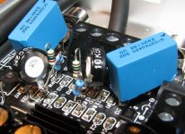
Here ya go, trimmer recipes:
Arjen's board:
for orientation put the board in front of you such that IN faces left and OUT faces right.
I use two 10k standing miniature trim pots
One goes right above the IN socket. Its left end is soldered to the ground rail, its right end is soldered to the left end of C17.
The center pin goes to the left end of R5 via a 1MOhm resistor.
The second pot sits right under the IN socket. The left end is again soldered the the ground rail. The right end I connected to the right end of the first pot via an insulated wire.
Center pin goes to the left of R6, again via a 1MOhm resistor.
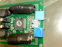
Sure board:
Here I have a different setup. Since the optimal position of the trimmer is very near the middle, I use two 20k resistors to either side of the pot. This way the output voltage is less sensitive to the tuning of the pot. So to be clearer (?) it is
+5GEN - 20k - pot - 20k - ground
orient the board such that CH2|GND|CH1 faces left and all OUTs to the right:
- remove R3
- shift R2 to the right such that the left end of R2 connects to the right pad of where it used to sit.
now you can solder the pot between the left end of R1 (or the left former pad of R2 or the left empty pad of R3) and the (now) right end of R2. Remember the right end of R2 now does not connect to any pad.
- center pin of this pot goes to the right end of R8 (or the right empty pad of of R3 or the left end of R7) via a 1MOhm resistor.
- remove R16
- shift R18 to the right such that the left end of R18 connects to the right pad of where it used to sit.
now you can solder the pot between the left end of R15 (or the left empty pad of R18 or the right empty pad of R16) and the (now) right end of R18. Remember the right end of R18 now does not connect to any pad.
- center pin of this pot goes to the left empty pad of R16 (or the left end of R13 or the left end of R14) via a 1MOhm resistor.
Hope I got all this right. Cook at your own risk.
Arjen's board:
for orientation put the board in front of you such that IN faces left and OUT faces right.
I use two 10k standing miniature trim pots
One goes right above the IN socket. Its left end is soldered to the ground rail, its right end is soldered to the left end of C17.
The center pin goes to the left end of R5 via a 1MOhm resistor.
The second pot sits right under the IN socket. The left end is again soldered the the ground rail. The right end I connected to the right end of the first pot via an insulated wire.
Center pin goes to the left of R6, again via a 1MOhm resistor.
Sure board:
Here I have a different setup. Since the optimal position of the trimmer is very near the middle, I use two 20k resistors to either side of the pot. This way the output voltage is less sensitive to the tuning of the pot. So to be clearer (?) it is
+5GEN - 20k - pot - 20k - ground
orient the board such that CH2|GND|CH1 faces left and all OUTs to the right:
- remove R3
- shift R2 to the right such that the left end of R2 connects to the right pad of where it used to sit.
now you can solder the pot between the left end of R1 (or the left former pad of R2 or the left empty pad of R3) and the (now) right end of R2. Remember the right end of R2 now does not connect to any pad.
- center pin of this pot goes to the right end of R8 (or the right empty pad of of R3 or the left end of R7) via a 1MOhm resistor.
- remove R16
- shift R18 to the right such that the left end of R18 connects to the right pad of where it used to sit.
now you can solder the pot between the left end of R15 (or the left empty pad of R18 or the right empty pad of R16) and the (now) right end of R18. Remember the right end of R18 now does not connect to any pad.
- center pin of this pot goes to the left empty pad of R16 (or the left end of R13 or the left end of R14) via a 1MOhm resistor.
Hope I got all this right. Cook at your own risk.
Thanks for the pictures, that is something I can work with. maybe we can workout a pictorial of all the mods to these boards (for the dummies that can't read)
Try reading.
The boards - esp. sure - are so crammed that surely the pictures aren't telling the whole story.
The boards - esp. sure - are so crammed that surely the pictures aren't telling the whole story.
Inductors
I will have alook for those this week, maybe i can find some nice sumida or murata parts.
i have equipment to test coils at work so i can see how good the are.
ill let you know!
u
GReetings,
Arjen
I will have alook for those this week, maybe i can find some nice sumida or murata parts.
i have equipment to test coils at work so i can see how good the are.
ill let you know!
u
GReetings,
Arjen
DC output
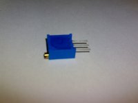
I can also look for some nice trimmers,
ive got some here that i can show
These are a bit smaller, this helps for sure.
I suggest not to use the connector for input but to solder directly to the board, this gives more space to work with.
I can make a upgrade set of 2 trimmer pots and
some 1 M ohm MOX resistors, 2 high quality input caps
and 2 X 10 000 uF tank caps.
This could be sold for 5 Euro.
Attachments
Arjen,
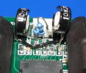
"this is how these small pots could be placed. a drip of hot melt glue, and there fixed to the board"
Nicely done.. Very professional.
Paul 🙂
"this is how these small pots could be placed. a drip of hot melt glue, and there fixed to the board"
Nicely done.. Very professional.
Paul 🙂
Re: DC output
This man is all about the profit 😉
This is a good idea too, add it to your parts list? I was thinking to buy trimmers etc anyway but this would save me £££ on ordering parts in the UK...
ArjenShenzhen said:I can make a upgrade set of 2 trimmer pots and
some 1 M ohm MOX resistors, 2 high quality input caps
and 2 X 10 000 uF tank caps.
This could be sold for 5 Euro.
This man is all about the profit 😉
This is a good idea too, add it to your parts list? I was thinking to buy trimmers etc anyway but this would save me £££ on ordering parts in the UK...
caps and pots
Hi Elfishy, good solution doh, if you see the things ive soldered together hahah a tropical rainforest is nothing compared to that 😛
I'd also love to re-design this board and make it DIY friendly all DIP parts and plenty of space for big caps and big resistors, trimmers on board and more copper plane for cooling.
i can get that done here,
but it needs time and money.
just let me think about it for a while and ill get back to you guy's
Toolkit, this set is more of a Fix, so i wont really be making much on it, as you can see by the price.
Luckely my Girlfriend is Chinese, so if we make 3 RMB profit i see big smiles, she is a sweetheart anyway ( Arjen, you are so good at making foreign friends! )
Greetings,
Arjen
I'm no expert on class-D amps, but isn't the design sensitive to the layout of the wiring (inductance, capacitance and stuff)?
So a more spacious layout could be detrimental, couldn't it?
So a more spacious layout could be detrimental, couldn't it?
ElFishi said:I'm no expert on class-D amps, but isn't the design sensitive to the layout of the wiring (inductance, capacitance and stuff)?
So a more spacious layout could be detrimental, couldn't it?
Absolutely, although the differences are subtle.
I've modified several of these T-amps TA2024 - TA2020 in various guises and I always try to get the input nodes as close to the pins as possible, as recommended by Tripath on their layout sheets.
Again, the output section is also very susceptable if the layout is wrong.
The Tripath sheets are worth reading.
As an example of just how far the components can be from the chip, see the Trends Amp........
An externally hosted image should be here but it was not working when we last tested it.
- Status
- Not open for further replies.
- Home
- Amplifiers
- Class D
- Sure Electronics Tripath boards?