PCB design
Thanks for that photo there,
i also think some extra space is not a big issue, id rather have the tank caps close doh, and the in and out put as seperate as can be. i did not read the Tripath appliation notes, but will do!
Greetings,
Arjen
Thanks for that photo there,
i also think some extra space is not a big issue, id rather have the tank caps close doh, and the in and out put as seperate as can be. i did not read the Tripath appliation notes, but will do!
Greetings,
Arjen
Sorry to interject but I have a situation that puzzles me.
I have two of these amps driving identical speakers.
Both work great.
One has a 16V laptop supply and the chip is cool to the touch.The other has a Canon printer 13.5V supply and after about 5 seconds I have to take my finger off the chip.I would have thought the lower voltage amp would be the coolest.
Just wondering.
Paul
Hot headed IC's
Hi there,
I am not to sure what could be the cause of a big difference in heat dissipation, i think to check the PCB for errors would be a good idea, and check the idle current. using the IC at 16 volts how ever is not reccomended.
One possible cause is perhaps a voltage difference at the input, when using a switching power supply it should be properly grounded.
Other than that, if there is any issue at the output of the IC, perhaps somthing is shorted . also try the IC at a lower voltage and see what hapens.
BTW, is this one of my boards?
Greetings,
Arjen
I just realized that the labelling of the components on Arjen's board almost completely follows the schematic of the T2024 evaluation board. Some are obviously missing (e.g. L1 ... L5), and e.g. C7 and C6 are swapped.
http://pdfdata.datasheetsite.com/web/27152/TA2024.pdf
http://pdfdata.datasheetsite.com/web/27152/TA2024.pdf
Re: Hot headed IC's
ArjenShenzhen said:Hi there,
I am not to sure what could be the cause of a big difference in heat dissipation, i think to check the PCB for errors would be a good idea, and check the idle current. using the IC at 16 volts how ever is not reccomended.
One possible cause is perhaps a voltage difference at the input, when using a switching power supply it should be properly grounded.
Other than that, if there is any issue at the output of the IC, perhaps somthing is shorted . also try the IC at a lower voltage and see what hapens.
BTW, is this one of my boards?
I'm sorry,I should have made it clear that they are the Sure Electronics boards.
Paul
Greetings,
Arjen
hijacking
Hi there paul,
Understand, no worries im kinda hijacking this thread with my pcb's, sorry about that!
but i suggest you try to debug it, somthing must be wrong. ususally the IC either functions, or it doesnt, there is not much in between, it might very well be dead....
if you want to solder this IC you will need a hot air solder iron so thats a bit of a pain.
The IC's here are about 2/3 euro's per one... almost the same like my board.
Greetings.
Arjen
I have connected both amps to the 16V supply and one still runs hot.
Both work perfectly.They are in use for a party tonight(bi-amp each channel),so I will check voltage offsets tomorrow.
I am using a brass bolt as a temporary heatsink and both are open mounted on top of the speaker boxes.
These are great amps and I'm getting more.
Paul
I think these little amps sound best at 16V supply,clearer and more precise.My daughters think so too.I've been using them for ages at this voltage(regulated of course)and have had no problems.
Touch wood.
That diode does drop the voltage a bit but you are running at the top of it's voltage limit. I personally would never allow more than 14V on constnt operation.
I'm sure earlier in this thread there was someone running these amps on 16V with no problem.
I'm using a 15-24V 3.5A laptop SMPS.
With polarity diode voltage drop that's 15.4V.
I have had no trouble with this.
Paul
I'm using a 15-24V 3.5A laptop SMPS.
With polarity diode voltage drop that's 15.4V.
I have had no trouble with this.
Paul
Thanks Franz, one thing is still not clear to me: in order to reach unity gain or something very close to it should I change some of the board resistors or just short a couple of the opamp's pins?
Unfortunately I still don't have the board in my hands...
Pincellone
Did you receive the board? Do you know, what to modify? I have one of them and could give you the needed hints, if desired.
My desktop T-amp project is moving slowly, as I had to repair my burned out Gainclone first (see http://www.diyaudio.com/forums/showthread.php?s=&threadid=125797 and use adequate fuses and switch of your equipment, when not in use!!!).
Here the layout of my desktop amp:
An externally hosted image should be here but it was not working when we last tested it.
Because the t-amp does not produce noticeable heat, its place is now under the buffer board.
The buffer is a J-Fet buffer with its own regulated psu (both from the seller tubeshunter / eBay). I will add a small print tranny in top of the torroid. I think a small tranny is sufficient as the buffer is running in Class-A and therefore comsuming nearby constant current.
Franz
The buffer is a J-Fet buffer
This was a kind of typo: it's a Fet buffer, not a J-Fet 🙄
Franz Gysi said:
Pincellone
Did you receive the board? Do you know, what to modify? I have one of them and could give you the needed hints, if desired.
My desktop T-amp project is moving slowly, as I had to repair my burned out Gainclone first (see http://www.diyaudio.com/forums/showthread.php?s=&threadid=125797 and use adequate fuses and switch of your equipment, when not in use!!!).
Here the layout of my desktop amp:
An externally hosted image should be here but it was not working when we last tested it.
Because the t-amp does not produce noticeable heat, its place is now under the buffer board.
The buffer is a J-Fet buffer with its own regulated psu (both from the seller tubeshunter / eBay). I will add a small print tranny in top of the torroid. I think a small tranny is sufficient as the buffer is running in Class-A and therefore comsuming nearby constant current.
Franz
Hi Franz, thank you for your help, I actually ordered a different item from Tubeshunter, but I'm still waiting for it. It has a gain of 20db, so I guess I need to find a way to make it reach unity gain instead. If you know how to do it, please let me know.
http://cgi.ebay.it/NE5532-HI-FI-STE...12050QQcmdZViewItemQQ_trksidZp1713.m153.l1262
How is your new buffer performing? Is the difference noticeable?
Thanks!
Pincellone
Hi Pincellone
Actually, I use the amp without buffer and it seems to work well.
I will try the buffer asap.
I have one of the same boards like you have, the opamp +20dB module.
So, should you have some questions modifying this board, dont hesitate to ask (me). 😀
I just remarked: the bypass caps are to far away from the pins of the chips.
It would be worth to add some good bypass caps directly at the pins to ground.
And to replace the ceramic caps by styroflex or mica types, should this caps really be needed.
Franz
Thanks Franz. It is still not clear to me if you actually tried the buffer I can see in the picture with the Sure board and whether or not you found an improvement by using it compared to a volume pot directly connected to the Sure (I'm using an Alps Blu RK27 25K as I was not satisfied with the performances of the 50k and 100k).
I hope to receive the preamp board soon, the only mod would be bringing it to unity gain and use it as a preamp for the sure board (if this is really worth it...) In that case it would be interesting to know what to modify to get lower the gain as much as possible.
Pincellone
I hope to receive the preamp board soon, the only mod would be bringing it to unity gain and use it as a preamp for the sure board (if this is really worth it...) In that case it would be interesting to know what to modify to get lower the gain as much as possible.
Pincellone
Zigis, thanks for the info.
I don't have the schematics of the preamp, but it seems to me that I should connect some pins of the dual opamp and remove a couple of resistors. Is that correct?
If so, could you please let me know which ones are they?
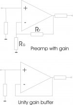
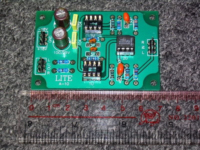
Here is the pinout of a dual opamp and the picture of the preamplifier. Thanks!
I don't have the schematics of the preamp, but it seems to me that I should connect some pins of the dual opamp and remove a couple of resistors. Is that correct?
If so, could you please let me know which ones are they?
Here is the pinout of a dual opamp and the picture of the preamplifier. Thanks!
An externally hosted image should be here but it was not working when we last tested it.
Yes, you need to remove 4 resistors for stereo, hard to say by photo which one, PCB is 2 sides.
Wen you get amp, find 2 resistors who go from pin 1 to pin 2 and from pin 7 to pin 6 and remove.
Than find 2 resistors from pin 2 to ground and from pin 6 to ground and remove both.
Then connect pin 1 to 2 and 6 to 7.
Zigis.
Wen you get amp, find 2 resistors who go from pin 1 to pin 2 and from pin 7 to pin 6 and remove.
Than find 2 resistors from pin 2 to ground and from pin 6 to ground and remove both.
Then connect pin 1 to 2 and 6 to 7.
Zigis.
- Status
- Not open for further replies.
- Home
- Amplifiers
- Class D
- Sure Electronics Tripath boards?