I was planning to make my next amp and recase my DAC in the hifi2000 stuff. The 10mm front panel options they offer I really like. No visible screws.
10k volume controll
Thought I should warn you that stock Sure TA2024 does NOT work well with a 10k attenuator.
The sound was so bad that I first thought I've burned both tweeters.
But then I realized there was something very wrong with the amp.
Sure Electronic support have been very friendly and supportive when I e-mailed.
But today I decided to run one more test before I returned the board as faulty.
Testing the amp without my LC Audio attenuator reviled that the 10k impedance of
the attenuator does not work well with the 100nF C2, C24. Nearly all treble was missing.
Removing these cap's and the amp now show potential.
DC on output was tamed from 548/614mV to 43/58mV by removing R3/R16.
As other have already mention, - as an old SI5066 user I feel there is some magic missing.
But it could also be that I just need some more time to get used to the way better low end this board presents stock.
My cheep DMM show input cap at 1,1uF on this v1.2 board.
Thanks justblair and ElFishi
It's funny, I had the Conrad cataloge just two meters away. The boxes from conrad looks nice and has a reasonable price. I think I will go for them.
The problem with the Asia Engineer is that they only have small boxes.
My thought is to put one of theese power supplies in the box I buy
http://cgi.ebay.com/ws/eBayISAPI.dll?ViewItem&ssPageName=STRK:MEWAX:IT&item=260265154593
Having two units; one for power supply and one for the amp.
Thos power supplies come in the same casework as the ones that sure sell. The sure ones are branded meanwell, but the cases look identical.
The outputs are laid out in the same way with what looks like the same trimmers....
The naming convention is very similar as well
HS-{insert wattage}-{insert Voltage}
as opposed to
S-{insert wattage}-{insert Voltage}
I'm guessing they come out of the same plant...
The outputs are laid out in the same way with what looks like the same trimmers....
The naming convention is very similar as well
HS-{insert wattage}-{insert Voltage}
as opposed to
S-{insert wattage}-{insert Voltage}
I'm guessing they come out of the same plant...
Varisign wrote:
Right now i had correct it till the small plate broken.
From the above I assume you Fixed it. ?? What was wrong ?? .
I also assume "small plate broken" means you have now overheated & lifted a Pad ??.
You can easily fix that by hard wiring to the next component. Just follow the circuit & solder in a jumper wire.
Yes Arjen's boards are easier to modify & the input cap's are mounted on the board.
The circuit is basically the Tripath EB-TA 2024 Evaluation board less the inductor in the input low pass filter by memory. I haven't looked too hard at the output side yet though.
You can download that circuit off the Web.
Paul
I just finished my desktop amplifier, including volume poti (stepped attenuator) and a FET buffer (http://cgi.ebay.com/ws/eBayISAPI.dll?ViewItem&rd=1&item=120230964247&ssPageName=STRK:MEWN:IT&ih=002)
The result is as expected: the volume poti's behaviour is now like it should be: logarithmic.
And the sound reproduction seems now to be more accurate, less harsh specially at lower and low levels.
I modified the buffer print slightly: removed the (low pass) ceramic caps at the input (but some twisted input cables inside, I measured 20pF).
And replaced the yellowish 0.01uF bypass caps by 1uF Wima MKP's.
Conclusion: it is worth to add a good (unity gain) buffer in front of the TA-2024, when using a volume pot.
Franz
Gain
Hi!
If one where to use several of these amps in a cinema setup one would need to be able to fine adjust the gain for each amp.
Could this be done simply by connecting a 10k pot in parallel with the 22k at R8 and R14 ?
Hi!
If one where to use several of these amps in a cinema setup one would need to be able to fine adjust the gain for each amp.
Could this be done simply by connecting a 10k pot in parallel with the 22k at R8 and R14 ?
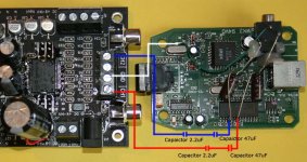
I want to connect a external usb sound card directly to my amp.
I bought the sound card at ebay:
http://cgi.ebay.com/PCLINK-USB-DAC-...ryZ96887QQssPageNameZWDVWQQrdZ1QQcmdZViewItem
I have two questions.
1.
If you look at the UDA 1321 data sheet (page 37) it is written that you should connect a 47uF capacitor after the audio output. But since I'm going to connect it to the sure electronics t-amp with the 2,2UF capacitors, will the 47uF really be necessary?
http://pdf1.alldatasheet.co.kr/datasheet-pdf/view/19847/PHILIPS/UDA1321PS/N101.html
2.
Since the power that comes from the USB is full of noise Im thinking of taking the power from the same source as the amp using a voltage regulator. Would this be a good idea? Will the computer be able to detect the sound card?
If I choose to use the power from the USB the ground will be different? Can i still connect the white cable (in my picture) to signal GND in the amp? What should I look out for?
// perco
Attachments
I messed up a little bit and damage C21´s right pad.
Where i can now put the input cap another end,if i want to use Sure´s own RCA connectors?C21 left and R14 right are next in input signal line,i suppose.
Left channel(C3->C13) is working ok.
Where i can now put the input cap another end,if i want to use Sure´s own RCA connectors?C21 left and R14 right are next in input signal line,i suppose.
Left channel(C3->C13) is working ok.
Camoon Wrote: I messed up a little bit and damage C21´s right pad.
Where i can now put the input cap another end,if i want to use Sure´s own RCA connectors?C21 left and R14 right are next in input signal line,i suppose.
The Signal originally fed through C21 left pad to C21 Right pad then to right pad on R14.
You can therefor put your new Cap between C21 Left Pad ( or the RCA Connector ) & R14 Right pad. OK?? You can check that with a DMM.
Audio 1st posted a full input & output circuit diagram of this board many posts back. Search his postings.
Paul
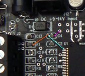
If the pad of C4 has been destroyed,do you know an alternative for connecting the capacitor?
It's not for me, but a friend of mine is asking around and I'd like to help him out...
It's not for me, but a friend of mine is asking around and I'd like to help him out...
Pincellone wrote: If the pad of C4 has been destroyed,do you know an alternative for connecting the capacitor?
C4 is the supply decoupling cap from V5D (pin 4) to Gnd. The right hand pad, (Chip side) is @ Gnd potential according to my DMM so I hope your mate, for his sake, has lifted that one. The closest unused hole in the board is also at Gnd potential so use that.
If he has lifted the other pad, he is going to need a steady hand & better eyesight than me to solder directly to Pin 4 .
C4 on my board measures 1.3 nF.
Paul
pincellone said:If the pad of C4 has been destroyed,do you know an alternative for connecting the capacitor?
It's not for me, but a friend of mine is asking around and I'd like to help him out...
If you are still having trouble here are the points to connect to;
Attachments
ZL2BPS said:
The Signal originally fed through C21 left pad to C21 Right pad then to right pad on R14.
You can therefor put your new Cap between C21 Left Pad ( or the RCA Connector ) & R14 Right pad. OK?? You can check that with a DMM.
Audio 1st posted a full input & output circuit diagram of this board many posts back. Search his postings.
Paul
Thanks for the reply.I have to also change R14 resistor itself,it´s broken.
I have an another decent sounding Sure amp,which has C3,C24 caps removed and an Elna Silmic 2 1000uf/25v caps in the power rails,so not big hurry to get that another one working.
audio1st said:
If you are still having trouble here are the points to connect to;
Thanks Audio1st!
hello sureelectronic board modders
my go at one of these,was to seperate the decoupling farads for each channel.I cut through the copper on the underside of the board,right in the centre where they are linked by 1cm wide trace.
Then I soldered two equal length wires (about 7cm)from each trace directly to the power take off pin on the bottom left side.I
thought it improved the sound.
A "NO SOLDERING" method. . .
If you're going to use this with your PC, TV or MP3, there's a super-easy way to make a big difference without soldering.
Parts:
A 470uF low-esr radial capacitor (16v, 25v, or 35v)
A 10uF low-esr radial capacitor (25v, 35v, or 50v)
*Other advertisement terms for "low-esr" include "made for audio" and "made for power."
A 12vdc 1+ amper "wall plug" (from my Linksys wireless router)
SURE Tripath amplifier board
First:
Crunch away R3, R16, C3, C24.
Second:
Install the 470uF capacitor into the screwdriver DC terminals, right next to the round barrel connector (where you plug the power). Fit (trim) nicely so that the cap isn't hanging out on its leads. The cap's stripe goes to negative as is printed on the board.
*With this, I was after a low, tight, bass and getting rid of treble errata, and this size cap is unlikely to make a midbass bloom/blur like most larger size caps.
Third:
Install the 10uF capacitor into the screwdriver DC terminals that are on the opposite side of the board from the power cord.
*With this, I was after a bit more clarity in the midbass. The 10uF "made for audio" cap isn't required for good sound, but as it does get warm, I think its saving some wear on the tripath chip, that is now running cooler.
That's it. Too easy! 😀
I feel real improvement of bass only wen I put 6800mf on power input terminals. I try 470 before, very small difference.
Interesting, I solder 3 x 470 on both sides parallel smd caps, small difference, again, wen I connect and disconnect 6800 on input - large difference in bass.
I don't feel I loose something in midrange or highs. This is not Gainclone.
Great improvement is soldering two low esr 470mf close to chip.
I replace 100mf in Arjen's board with Rubycone 470mf, great improvement, even with stock input caps.
Zigis.
- Status
- Not open for further replies.
- Home
- Amplifiers
- Class D
- Sure Electronics Tripath boards?