tobias_svensk said:Or make one whole board that just has one relay that switches a couple of seconds after you press the button./T
That's the one.......
Isn't there an off the shelf microcontroller circuit that can do all this?
You could just use a low end PIC microcontroller($0.50), a 7805 regulator($1) and a relay($1).
Here is an example using a PIC with C code.
http://www.egr.msu.edu/classes/ece4...tion_notes/Cammi_Stewart_Application_Note.pdf
Alternatively you could use a 555 timer, but the component count would be higher.
Amp up and running
Recieved my new toy. Fired it up for a bit of burn in, after a cleaning. Ran it for about 8 hours, removed R3/R16, and C3/C24, ran another 8 hours. Turned this thin on this morning, and it sounds like a different amp. The staging on this thing is great, considering what it is pushing at the moment. The odd thing is this, before and after removing R3/R16:
Ch1 before 315mv after 7mv
Ch2 before 205mv after 115mv
May have something causing the 115mv, will have to go through the board measuring. Has anyone else run into similar numbers?
audio1st said:Finished the Headphone amp, does the job. No idea how good it is, have neither the good headphones or another good headphone output to compare it to, it is revealing tho..😱
More info please - I ordered one of the 8w amps also, I was wondering if I could drive some hd600's with it. 🙂
Is there any way to utilize the sleep and mute terminal on this board? If so how?
I think that you need to connect them to VDD, but check the datasheet for the chip first.
Sleep anyone get it to work?
Reviewing the TA2024 datasheet I see the SLEEP Input Voltage is -0.3 to 6.0v.
The datasheet also says the following
"Sleep Pin
The SLEEP pin is a 5V logic input that when pulled high (>3.5V) puts the part into a low quiescent current mode. This pin is internally clamped by a zener diode to approximately 6V thus allowing the pin to be pulled up through a large valued resistor (1megÙ recommended) to VDD. To disable SLEEP mode, the sleep pin should be grounded. "
I measured the voltage at J14 VDD and GRD and got 12v, so I assume J14 VDD terminal can not be connected directly to J14 Sleep terminal initiate the sleep.
Post #24 (http://www.diyaudio.com/forums/showthread.php?postid=1374517#post1374517) and Post #181 (http://www.diyaudio.com/forums/showthread.php?postid=1396009#post1396009) touch on utilizing the Sleep terminal. Both indicate that a direct connection from J14 VDD terminal to J14 Sleep terminal is not advisable.
So anyone have any suggestions on whether I can wire my momentary push-button to control sleep mode on this board?
Your datasheet quote answers the question - by connecting VDD to the switch, then connecting the switch to the sleep terminal via a 1megOhm resistor.
It appears from the schematic posted on Post #61 (http://www.diyaudio.com/forums/showthread.php?postid=1384052#post1384052) that the sleep pin is connect to a gnd via a R17 22K. I tested this with my multimeter and it does appear the chip sleep (pin18) is connected to the J11/J14 GND terminal via R17. Should I remove R17 before adding the switch and 1 megOhm resistor?
Hi nbrophy, for sleep to work you would need to remove R17, replace it with C25. Then replace C25 with a 1M ohm resistor. This will keep it in sleep mode until the sleep terminal is connected to ground. This will not help you with your "momentary" switch because it must be permanently connected to ground to stay working..Sorry..
Attachments
What does the extra on the power rails do? Is it similar a tank cap? Currently I am using a Panasonic FM Capicitor 680uF from digikey as my a tank cap.
A buddy and I finally finsihed this thing up at 4am. We had some wiring issues initially but we were both quite happy with the sound.
The DC offset is less than my Sonic Impact now and the sound is pretty rich and full. I have it on the output of my tube-pre right now burning in...the unit itself only has about an hour and the caps about half that.
I put the caps on terminals so I could try different brands. Last night alone we tried the Solens, Solens with Sonicap .47uf bypass, and Auricaps by themselves. It sure was handy!
I gotta clean up my rats nest, but other than that I am happy.
Oh yeah, I know my knob is lame...I am still looking for the "right" one.
An externally hosted image should be here but it was not working when we last tested it.
An externally hosted image should be here but it was not working when we last tested it.
nbrophy said:What does the extra on the power rails do? Is it similar a tank cap? Currently I am using a Panasonic FM Capicitor 680uF from digikey as my a tank cap.
Hi nbrophy,
Yes, I just added a 1000uF to each side.
Hi billnchristy, the changeable caps are a good idea and your knob looks OK to me😉 😉
Hello,
Just finished the enclosure for my board. It's a pretty tight fit and the volume knob still needs to be replaced.
Mods: Removed C3, C4. Added 2200uF to the rails. Removed R3, R16 and DC offsets are approx. 2mV and 30mV.
Just finished the enclosure for my board. It's a pretty tight fit and the volume knob still needs to be replaced.
An externally hosted image should be here but it was not working when we last tested it.
An externally hosted image should be here but it was not working when we last tested it.
An externally hosted image should be here but it was not working when we last tested it.
An externally hosted image should be here but it was not working when we last tested it.
Mods: Removed C3, C4. Added 2200uF to the rails. Removed R3, R16 and DC offsets are approx. 2mV and 30mV.
ON / OFF/ ON DPDT For Power Switch?
Can this be used as power switch for my board?
http://cgi.ebay.com/ws/eBayISAPI.dll?ViewItem&rd=1&item=120239711570&ssPageName=STRK:MEWA:IT&ih=002
Can this be used as power switch for my board?
http://cgi.ebay.com/ws/eBayISAPI.dll?ViewItem&rd=1&item=120239711570&ssPageName=STRK:MEWA:IT&ih=002
Can this be used as power switch for my board? http://cgi.ebay.com/ws/eBayISAPI.dl...:MEWA:IT&ih=002
Looks fine to me, it's a Bulgin latching DPDT. I used the same switch with mine (but the one with an LED in the middle) and it works great.
Here are a couple of pics with the top on:
An externally hosted image should be here but it was not working when we last tested it.
An externally hosted image should be here but it was not working when we last tested it.
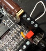
Found a easiest way to mute the startup pop noise.
Need 2 way on switch and 330uf/6.3V cap.
12V to center, one way to 12V supply on board when (ON), the other goes to mute connecting point on board (OFF), connect the 330Uf to pin 12 and ground.
No more startup noise
R9/R12 must present 20K.
Need 2 way on switch and 330uf/6.3V cap.
12V to center, one way to 12V supply on board when (ON), the other goes to mute connecting point on board (OFF), connect the 330Uf to pin 12 and ground.
No more startup noise
R9/R12 must present 20K.
Question:
I am going to have to assume that the 3 power caps on each side are parallel right?
If that is the case couldn't you just add one across the "plug" instead of soldering onto the existing ones?
Please kick me if I am wrong...just explain why while you are beating me mercilessly. 😉
I am going to have to assume that the 3 power caps on each side are parallel right?
If that is the case couldn't you just add one across the "plug" instead of soldering onto the existing ones?
Please kick me if I am wrong...just explain why while you are beating me mercilessly. 😉
- Status
- Not open for further replies.
- Home
- Amplifiers
- Class D
- Sure Electronics Tripath boards?