Hi everybody from a newbie !🙂
First I want to thanks all for the enourmous quantity of information that is possible to fnd here, then a
brief story : last month, making order in my garage i foun a couple of coaxial car speakers so I questioned
to myself : " what about to make a good cheap and good sound docking station for my new Iphone ??" .
surfing the web I discovered the T-amp and looking on ebay I founded some little boards with the 2024 chip,
I bought one froma a vendor named " Iwannabuy" that seemed to be the Sure but , after I read this thread I
discover to have a CLONE .
I would like to make some mods to the board like :
a) removing the C3 and C24
b) remove and bridge C3 and C21 adding a good cap of 2,2 mf in line of + signal
c) remove R3 and R16
d) to add ( replace ?? ) capacitor to the power rails ( here I've not clear ideas HOW to make the mod and WHAT exactly I've to add...:-( )
e) substitute the inductance with bigger ones ( do this really help ? wich kind of inductance is good for it ? )
But as you can see many components are in different position respect to the Sure board so I don't know if is still possible to make the some mods of the sure....
I know that someone else have my same board like gychang ...
Does anyone can help me ?
Thanks
Just for you gychang😉
Hey guys. I received my Sure 2024 amp module a couple of days ago. I got all the parts for my enclosure and also wanted to do the above mods according to the illustration by audio1st above.
I went to an electronics store and showed them the diagram and they gave me me a 4,700uF 63V Electrolytic Can. I dont think they had a 16v so they gave me this instead. Will the 63V electrolytic be fine?
I also got a LED but its not 12V, what sort of resistor do I need to connect it to a 12VDC power supply?
Sorry for the double post, its the first time I posted and didnt think it worked the first time.
I forgot to ask, how to I know what is positive or negative on the electrolytic? The leads are the same length. It has leads like the one in this picture:
I forgot to ask, how to I know what is positive or negative on the electrolytic? The leads are the same length. It has leads like the one in this picture:
An externally hosted image should be here but it was not working when we last tested it.
Hi, would a sure electronics 2024 T-amp benefit from a 12v dc shunt regulated PS? I'm thinking of combining the T-amp with one of my dcb1 buffers.
Would a linear PS be just fine?
Would a linear PS be just fine?
Linear would be just fine. A shunt would be big. A 3 amp supply works well with these chips. They rarely draw that much, but more current on tap seems to sound better.
Capacitor markings
The arrows point towards the negative pole. i.e. the end in the photo that has the 4.0 over 2200 at the right hand side is the negative lead.
The arrows point towards the negative pole. i.e. the end in the photo that has the 4.0 over 2200 at the right hand side is the negative lead.
this one works fine for me on a Sure TA2024 Board..
You might have to Snip the Leads tho..
Canon Ac Adapter AD-360U K30088 FREE SHIPPING - eBay (item 250634348259 end time Jun-15-10 19:39:26 PDT)
You might have to Snip the Leads tho..
Canon Ac Adapter AD-360U K30088 FREE SHIPPING - eBay (item 250634348259 end time Jun-15-10 19:39:26 PDT)
Last edited:
I need some help...
I removed C3,C24, C21 and C13. Is it a must to bridge C21 and C13?
I then removed R3 and R16 to lower DC offset aswell
Then added 10k resistors to R8 and R14.
The problem is now I cannot get any audio... I used a tester and saw that there is current throughout the board however there is NO power coming out of the speaker terminals!?... any ideas what could have caused this? Earlier I tested and saw there was power but could not seem to get it back after that...
Please help, thanks
Last edited:
I will post pics of the amp in the morning.
Just a side note, I did not bridge C21 and C13... could this be the cause of me getting no audio?
Just a side note, I did not bridge C21 and C13... could this be the cause of me getting no audio?
Last edited:
Are there any guys still active, I would really appreciate the help.
Unfortunately my camera cannot take good pics and if would be rather useless to post it.
I did some more experimenting, as posted earlier I have C24 and C3 removed, R8 and R14 have 10k resistors and c13 and c21 are temporally bridged.
I noticed that I can see a sort of brown through the solder on C21 and C13 which is probably the pcb... I hope this is not the fault.
I notice that without an input there is a slight hum on the speakers but when I connect an input (my cellphone), there an extremely loud buzz. I am using a 3W 4ohm test speaker because I dont want to mess up my other speakers. The speaker terminals are still not showing a + or - on my tester aswell.
any ideas?
Hi there.. the correct pot should be 50k. After this nothing but a filter choke (two for stereo) from live input to ground. Value 2000henry/47kohms. This is a recipe somewhere found on tube circuitry when placing a grid choke on input tube to ground. Then input capacitors, I find the best to be teflon from russia (4 x 0,47uf.) + 0,22uf. What more.. ah! yes there is on input chip four resistors R 8-14-7-13, I got 33kohms on this. This is enough for the input.
Hi guys,
what is the needed voltage rating for the output 0.47µF caps?
16V DC will do on this tiny amp?
Thx,
Matthieu
what is the needed voltage rating for the output 0.47µF caps?
16V DC will do on this tiny amp?
Thx,
Matthieu
I am looking at the pre-built Sure amp with the AA-AB340 board, can someone tell me if that is an opamp buffer stage on board?
According to the circuit schematic - No!
It looks like Sure Electronics has a new (and improved?) version of this board. They claim:
It integrates a high-quality potentiometer and a rotary encoder which provides precise shaft rotation. This potentiometer employs high-quality digital volume control IC ensuring more accurate volume adjustment and perfect sound output than the traditional analog potentiometer even after long time use.
I wonder what that means. You can see some of the difference on the circuit board. It looks like they may have made a few small tweaks to the power end of the amp as well. Look at the box caps used on the supply rails to the Tripath chip.
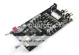
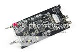
-Old board- -New board-
Hi guys,
what is the needed voltage rating for the output 0.47µF caps?
16V DC will do on this tiny amp?
Thx,
Matthieu
On bridged amps they need to be twice the supply voltage, on a single ended amp the rail-to-rail voltage...(positive and negative rails....)
It looks like Sure Electronics has a new (and improved?) version of this board. They claim:
I wonder what that means. You can see some of the difference on the circuit board. It looks like they may have made a few small tweaks to the power end of the amp as well. Look at the box caps used on the supply rails to the Tripath chip.
-Old board- -New board-
Often volume controls with IC are done with + and - buttons. A nicer interface is the rotary encoder, which gives the feel of a pot, but actually does nothing other than pressing the volume up and down at the IC pins...
Usually these encoders don't have an end stop and can be turned infinitely, so the volume often returns to a pre-fixed setting on start up. If not there may be a memory holding the last setting, but then (and in any case) it would be handy if there was a display showing the level....
I would ALWAYS prefer to have a separate preamp and not have all this junk on my power amplifier board, but for portable devices and PC speakers it can be convenient....
Sure should offer the encoder and IC volume buffered on a separate preamp board. Maybe with selectable gain (maybe 1x, 2x, 4x)? Then I'd just have to find a worthwhile DPDT input switch to go with it.
Seems like it would be fun.
Seems like it would be fun.
Sure should offer the encoder and IC volume buffered on a separate preamp board.
Don't forget the IR remote control.
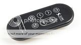
http://i69.photobucket.com/albums/i43/Ty_Bower/SureElectronics/RMB-CM11111_1_b.jpg
Last edited:
Have a look at DIYGene's remote kits on Ebay! They're quite nice!! They are just remote kits, he's got buffers and preamps too to combine with them....
On bridged amps they need to be twice the supply voltage, on a single ended amp the rail-to-rail voltage...(positive and negative rails....)
Not any of these case here, isn't it? So my 16V caps should do fine.
Thanks!
- Status
- Not open for further replies.
- Home
- Amplifiers
- Class D
- Sure Electronics Tripath boards?