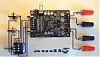
New Tripath Board based on TK2050
see my post here:
http://www.diyaudio.com/forums/showthread.php?s=&threadid=143669
see my post here:
http://www.diyaudio.com/forums/showthread.php?s=&threadid=143669
ERO MKP 1839
I have a question...
Per Humble Homemade Hifi, it is good to use the MKP 1837 / 0.01uf in parallel with another cap. In my case, I stumbled into some MKP 1839 / .33uf (mkp1839 is the coaxial version of mkp1837), could I use these instead? at .33uf instead of .01uf? Any major problems?
Thanks in advance for the expertise.
John
audio1st said:
It sounds bad because of C3 & C24, they are 100nf caps across the supply and cause a passive volume control to act as a tone control..REMOVE C3 & C24..
Hello Lee, I don't know what all the 22k resistors are for yet, DC offset is about 500mv on both boards I've got..
I found out I had this board laying around, glad to find this thread and helpful folks.
1. I will remove the C3, C24.
2. How do I measure DC offset?, I have a meter but use it mainly to measure resistance...
3. Can this amp after the mod sound "better" than modded t-amp?
thanks
gychang
Peter Menting said:FWIW; I have enjoyed some success removing small SMD components using a sharp pointed X-Acto knife blade. I place the blade tip at the intersection of the chip and board and apply heat to it, sliding the iron down the blade toward the component but not touching it or the board. At some point the adhesion surrenders and the SMD simply "pops up" without damaging the trace.
Hope this helps.
Pete
Pete, this is a valuable tip, since I have removed the solder pads before. Will this work to save the pad and remove just the SMD?
gychang
Do not apply too much prossure with the razor and you should be fine. Be gentle so that you do not pull up the other side of the SMT too far and damage the pad or the device.
Cheric,Per Humble Homemade Hifi, it is good to use the MKP 1837 / 0.01uf in parallel with another cap. In my case, I stumbled into some MKP 1839 / .33uf (mkp1839 is the coaxial version of mkp1837), could I use these instead? at .33uf instead of .01uf? Any major problems?
There should be no problem using the 0.33 μf caps in lieu of the 0.01 μf caps. Be sure the cap is used as a bypass (in parallel). In my experience the 0.01 μf should yield a tinge more sparkle to the highs, but most likely it will be hard to discern the difference.
I thought this thread was about Sureelectronics boards?!
Very nice looking amps there anyway Arjen!
Those Sureelectronics boards sure need a lot of mods!😉
http://www.justblair.co.uk/classdamplifiers/index.html
Very nice looking amps there anyway Arjen!
Those Sureelectronics boards sure need a lot of mods!😉
http://www.justblair.co.uk/classdamplifiers/index.html

Hey gychang,
Check out post #206 in this thread. There is a diagram there that has all the basic mods for this board. The best part is all the components that you need to remove or change are highlighted. It makes it real easy.
Check out post #206 in this thread. There is a diagram there that has all the basic mods for this board. The best part is all the components that you need to remove or change are highlighted. It makes it real easy.
gurley123 said:Hey gychang,
Check out post #206 in this thread. There is a diagram there that has all the basic mods for this board. The best part is all the components that you need to remove or change are highlighted. It makes it real easy.
are u sure it is #206, attached picture?
gychang
Attachments

audio1st said:Here is the basic volume control circuit. If you bridge C13 & C21, then add your new caps between the pot and CH1 & CH2 inputs, red and black wires..
thanks for your excellent photos.
I have 2 caps, 3.3uF, 50V. Can these be used for C13 & C21? (I don't have 2.2uF). I plan to remove and bridge the original C13 & C21 and solder them on the input side on CH1 & CH2.
thanks,
gychang
Attachments
bongoman said:I'm using an IBM Thinkpad 16V supply, but that's on the edge of what the board can take so just be careful!
I have a laptop adapter 15V 1.5Amp, what sound affect can be expected with lower amperage?
gychang
gychang said:
I have 2 caps, 3.3uF, 50V. Can these be used for C13 & C21? (I don't have 2.2uF). I plan to remove and bridge the original C13 & C21 and solder them on the input side on CH1 & CH2.
gychang
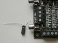
1. Attaching the caps as pictured work? (plan to use for both channels of course)
2. Does it matter which cap "leg" is toward the PCB? One is longer.
3. Unrelated question of attaching the heatsink without screws. Is the a special compound with bonding property that transfer heat? I am unsure how to "glue" the aluminum.
gychang
Attachments
Hi gychang,
if you have original input caps C13, C21 in place, you don't need any additional input cap, just connect signal to input.
To improve sound quality more, bypath C13, C21 and connect quality non polarized film cap, search for metalized polypropylene or at least metalized polyester.
Electrolytic cap (you have in pic) in this place can't made any sound improvement, even worse than original.
Zigis said:Hi gychang,
To improve sound quality more, bypath C13, C21 and connect quality non polarized film cap, search for metalized polypropylene or at least metalized polyester.
This is very helpful comment. Mods so far sound is significantly improved from the original. I am however interested in improving it little more by replacing C13, 21.
can someone recommend a web site for the correct part (metallized polypropylene caps?), MCM, partsexpress or ebay (as part of package deal?)
gychang
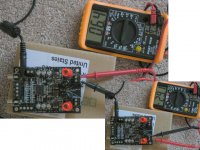
anything wrong here?
Partly modified board sounds very good to me, compared to my recent Pioneer Elite and professionally modified amp32, playing on my large speakers.
I measured the voltage output with the DC input, but I get markedly different values on the speaker side. Values are same whether I measure from the banana plug or the terminal side.
Is there a reasonable explanation or does it matter at all since the sound is very good.
thanks in advance.
gychang
Attachments
- Status
- Not open for further replies.
- Home
- Amplifiers
- Class D
- Sure Electronics Tripath boards?