Measure volts with the amp turned on with the black probe on ground and then touch the red probe to each speaker terminal one at a time. They should all read half of the supply voltage.
Thanks much ...
Measure volts with the amp turned on with the black probe on ground and then touch the red probe to each speaker terminal one at a time. They should all read half of the supply voltage.
Hi I am again. Measurement is done. I read 0 volts and the board still makes this buzzing after a while. This cannot be normal or ?
I contacted support again. Hope this time to get the reply a bit earlier.
Input voltage
Is there any voltage from the supply? At least at the beginning when first turning it on?
Hi I am again. Measurement is done. I read 0 volts and the board still makes this buzzing after a while. This cannot be normal or ?
I contacted support again. Hope this time to get the reply a bit earlier.
Is there any voltage from the supply? At least at the beginning when first turning it on?
If they would read half the supply voltage, dc offset would be the Vcc, effectively killing your speakers...
Can you locate the buzz?
Can you locate the buzz?
offset
They should all 4 read 1/2 supply voltage. ie all four speaker outputs should be at 15v to ground. This makes no difference between them. 0v offset. Do you have one of these amps? You would know this.
If they would read half the supply voltage, dc offset would be the Vcc, effectively killing your speakers...
Can you locate the buzz?
They should all 4 read 1/2 supply voltage. ie all four speaker outputs should be at 15v to ground. This makes no difference between them. 0v offset. Do you have one of these amps? You would know this.
Is there any voltage from the supply? At least at the beginning when first turning it on?
Yes. I measured in the end solid 22,7 V. That must have been also in the beginning because my SMPS shuts down the voltage if no load is registered.
BTW: there are two GND points on the board. I took that one where the SMPS
(-)cable leads in. The other GND point (Mute) is on the opposite side you know (+5V;Mute;GND)
Measurements
So, you have 22v on the voltage in connector, and 0v from any of the speaker connectors to ground and I assume that the 5v is wrong as well since the fan quits. You can check the voltage on the output side of the big diodes that are right near the power input but I doubt that they are blown. It should be .4v less than the supply.
excuse me: THREE GND points !The third was between the Input channels..🙄
So, you have 22v on the voltage in connector, and 0v from any of the speaker connectors to ground and I assume that the 5v is wrong as well since the fan quits. You can check the voltage on the output side of the big diodes that are right near the power input but I doubt that they are blown. It should be .4v less than the supply.
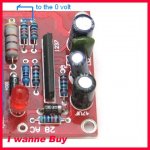
Thanks till now, which diodes you mean look please:
An externally hosted image should be here but it was not working when we last tested it.
Last edited:
Yes
Yes.
Thanks till now, which diodes you mean look please:
An externally hosted image should be here but it was not working when we last tested it.
Yes.
Hi all,
I've hooked up the sure board to the MeanWell 36v (tuned back to 32v) and changed the input as per Audio1st's recommendations (although I've used Wima MKP10 2.2's) and changed to the Wurth XXL coils on the output stage. Furthermore there's 3x 470uF of Simlic II caps on each side. Currently there is no big cap tank, although I'll add 20mF when I finish the supply.
The sound is VERY clear, it's by far one of the most detailed amps I've ever heard and I'm pretty happy with it in that respect.😀
However I think the bass is a bit lacking. Any tips on improving that? 😕
(Note that it's currently running without the tank caps but I don't think that's going to make the difference, I dare not connect them as long I've got no power-off-mute circuit in place, my test speakers popped massively and I don't want to do that to my main speakers... 🙄).
Bass shy
That is a good question. I have noticed this as well and did end up bumping my eq up a db from 100Hz. I have been pondering this and don't know if I think it is really a supply cap issue or something on the input. It could be the way the dc of the input is interacting with the cap. An easy test would be to use a huge input cap such as 15uf to hear if this makes any difference.
.
A friend loaned me his little tube amp which made an interesting comparison. The tubes create very palpable, solid images and have an over ripe bass from their higher output imdedance which can start doubling audibly at louder levels due to their limited power while the Class D amp seems to reach a bit deeper toward the noise floor in revealing the last bit of previously hidden information. And are much cheaper. The bass of the tubes gave me another idea. Maybe the Class D has such an iron grip on the output that some added output impedance might loosen up the bass and give subjectively more of it. I have been wanting to try paralleling both channels with added output resistors of .1 - .22ohms to find out if it will work with out dc and heat problems in order to get back the last of the weaker bass. I could also utilize both legs of my balanced source this way.
Turn on pop
I have figured out how to implement a $20 speaker protection board from Connexelectronics in order to eliminate the turn on/ turn off thump and will post the details when I receive the modules and get them wired up to make sure it works as I anticipate it will. Sometimes shipping from China takes quite a while. Larger input caps on the 2X100 increase the thump.
my test speakers popped massively and I don't want to do that to my main speakers... 🙄).
I have figured out how to implement a $20 speaker protection board from Connexelectronics in order to eliminate the turn on/ turn off thump and will post the details when I receive the modules and get them wired up to make sure it works as I anticipate it will. Sometimes shipping from China takes quite a while. Larger input caps on the 2X100 increase the thump.
I'm building something like that as well, I saw a nice reverse current sensor a couple of dozen pages back and that's going to be a poor man's turn-off-mute 🙂 The turn on is going to simply be a RC-timer attached to a relay. Lots of examples to pick from the thread and fun to build 😛
my test speakers popped massively and I don't want to do that to my main speakers... 🙄).
Ohh ... I am not alone with that appearing. This must not mean automatically a disadvantage. Many older (also expensive ones) british SS amps used to make this Popp by switching ON. As I know it was intended to keep the signal way pure.
In case of sure-electonics it could be reasoned by production costs and boardspace to without speaker relay ...😱
Hello,
to avoid the switch on noise,(for kt2050 sure kit ) i'm using a delay and ac delay (immediately switch off ) protect.
Speaker Protection Board for DIY Power Amplifier en vente sur eBay.fr (fin le 04-mai-10 21:02:12 Paris)
remove the two leads of 56k resistors and tie both to the 0 V terminal.
the DC protect can not work,but delay is ok.
it's working perfectly with swith on and ac switch off (with a linear supply )
based on a upc1237 chip speaker protection.
Attachments
Last edited:
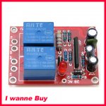
Speaker protection module
I ordered these speaker protection modules from Cristi at connexelectronic.
.
Connexelectronic
.
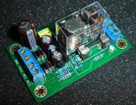
He is a good contributor to DIY Audio and makes some of the best designs. He has two amp modules which may be among the worlds best at any price with his 3020 amp and the LME49810 amps. I also purchased small transformers
.
Digi-Key - 567-1035-5-ND (Manufacturer - BV030-7329.0)
.
from Digikey in order to provide the dedicated power supply that is needed in order to allow the dc protection to work with the Sure 2X100 which is bridged so a floating 0v offset point relative to the dc level which is present on all four speaker terminals must be created.
I ordered these speaker protection modules from Cristi at connexelectronic.
.
Connexelectronic
.
He is a good contributor to DIY Audio and makes some of the best designs. He has two amp modules which may be among the worlds best at any price with his 3020 amp and the LME49810 amps. I also purchased small transformers
.
Digi-Key - 567-1035-5-ND (Manufacturer - BV030-7329.0)
.
from Digikey in order to provide the dedicated power supply that is needed in order to allow the dc protection to work with the Sure 2X100 which is bridged so a floating 0v offset point relative to the dc level which is present on all four speaker terminals must be created.
Attachments
Simple resistor divider
.
http://www.diyaudio.com/forums/clas...new-tripath-board-tc2000-tp2050-new-post.html
.
The center tap of a simple resistor divider on the amp power supply adjusted to match the dc on the speaker terminals will work fine to create the reference point in order to allow the dc protection to work.How about creating a virtual ground point using something like an lm317?
.
http://www.diyaudio.com/forums/clas...new-tripath-board-tc2000-tp2050-new-post.html
.
Hi and question for Sendler
Hi everyone,
I'm new - well to Class D (though have experience with building valve amps and other electronics) and bought all the bits-n-bobs for the Sure 2*100W.
So I spent a while reading through all 150-or-so pages and got to say I am really impressed by the great contributions and discussions. Everything is clear, but I just got a couple of small questions for Sendler and anyone else with similar experience.
I noticed Sendler mentioned on page 140 that R14 and R34 on the inputs should be kept as it sounds better than having them removed (as shown in audio1st's superb diagram). Was this kept due to a linear pot being used, or was it because of better impedance matching? I'll be using a 100k log pot and concerned whether it would present an additional law-faking resistor effect on an already logarithmic pot.
Also I know this is likely to be seen as an obvious question, but I'd like to double check - are R5 and R26 used to set the d.c. on the outputs to 0V?
Thanks for you help in advance. I got a really nice chassis from RS and hope to present the final pictures when I can. It's going to take a while though, a busy family life means having to pace myself through this build - which is no bad thing.
Other mods will be:
1) Wurth 4.7uH (I should be able to use the stock output caps for that?)
2) Zalman ZM-NB47J heatsink (removing the old one should give better soldering access to the inductors)
3) Input caps - will have a go at some 4.7uF metalised polypropylenes from LCR
4) Make further mods on the inputs (e.g. removing the suppressors)
Fingers crossed.
Not so sure about replacing the power rail ceramic caps with higher value electrolytics - using a 24V 350W Meanwell, which should be stiff enough. Also want to reduce the need of replace the electrolytics every 10 years.
Also, while I am here, if you're interested in finding some top notch chassis - have a look at Takachi - they're Japanese and I found them when I used to work for NEC and visit Japan now and then. I suspect though that import costs would be high 🙁 Here are some pdfs of some of their applicable stuff:
http://www.takachi-el.co.jp/data/pdf/04-11.pdf (I have a couple and they are top notch!)
http://www.takachi-el.co.jp/data/pdf/04-15.pdf
http://www.takachi-el.co.jp/data/pdf/04-19.pdf (more of a valve chassis)
Andrew Randle
The Hi-Fi Watcher
- Status
- Not open for further replies.
- Home
- Amplifiers
- Class D
- Sure Electronics New Tripath Board tc2000+tp2050