That could be it. I thought the voltage divider for the inverting input was R6/R7. And I never understood why R16 (100R) should not be taken into account in that voltage divider, as it is in series with both R6 and R7. Is that not correct?
A while back user dvd7900 helped me out in this thread with the voltage divider (here). For 30V output he (?) suggested 665R for R7 and 2.1k for R6. The excel sheet that I use for calculating the voltage divider yields 30V for both dvd7900's suggestion and my numbers.
Still, if only my output voltage came up short that could be it. But it should be stable, right?
The output is not stable. It is hovering up and down between 26V and 27V, varying by a couple hundred of mV. And if the only problem is that the voltage divider was calculated incorrectly, shouldn't the opamp still equalize the two input voltages? The inputs on mine are around 0.5V apart.
Plus everything on the output side of the opamp (BC556, D44H11, caps) is getting really hot. Much hotter than I would expect it to be with a 30mA load.
The opamp's suppy voltage is specified as +18V/-18V. Does that mean it should be able to handle 36V if the negative supply voltage is at 0V?
Did you use the diyaudiostore.com PCB or your own?
The unstable output we can look nat once we have Vout correct. Take it one problem at the time.
I assume that R6 and R7 are the resistors that divide down Vout and send that to the inverting input.
If you want to be exact, add R18 to R6 for the calculation.
Fix that first, when see what problems are left.
Jan
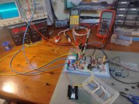
My own. I will try to build one tomorrow with the diyaudiostore.com PCB to see if there's a problem in my PCB layout or build / soldering. Will report back when I have been able to test this.
About R6/R7: I am referring to the REFDES in the schematic as it is in the diyaudiostore.com page for the superregulator board, this one:

I measure 21.3V over R6 and R16, not quite stable so hovering around that value. In my calculation it should be 23.1V (making a neat 30V with the 6.9V of the LM329).
Over R7 there is 6.34V. So here you see the 0.5V missing that the opamp isn't equalizing.
At the non-inverting input I measure 6.84V, so that's pretty decent considering that the LM329 actually measures 6.9V on my board.
About R6/R7: I am referring to the REFDES in the schematic as it is in the diyaudiostore.com page for the superregulator board, this one:
I measure 21.3V over R6 and R16, not quite stable so hovering around that value. In my calculation it should be 23.1V (making a neat 30V with the 6.9V of the LM329).
Over R7 there is 6.34V. So here you see the 0.5V missing that the opamp isn't equalizing.
At the non-inverting input I measure 6.84V, so that's pretty decent considering that the LM329 actually measures 6.9V on my board.
Yes that's the right schematic. Still I think the R6 and R7 values are not correct for 30V.
I said R18 in my previous post, should be R16 of course.
Jan
I said R18 in my previous post, should be R16 of course.
Jan
The R18/R16 mixup was obvious, so no confusion caused.
I'm relatively new at all this. Even tho this is a simple voltage divider it's easy to mess it up. The R6/R7 midpoint should be 6.9V, correct? So please correct my math:
(6.9/562)*1880=23.1V
or
(30/(1880+562))*562=6.9V
These work out to similar results with the 665R/2k1 combo that dvd7900 suggested.
Yes correct, I had the wrong values.
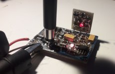
Another thing. You mentioned that the LED was very bright.
What's the value of R1 and what is the voltage across it?
Jan
Another thing. You mentioned that the LED was very bright.
What's the value of R1 and what is the voltage across it?
Jan
No, that LED thing was my own mistake. I looked at it straight from above making it look brighter than it is from the side.
R1 is 249R as in the schematic. There is 2.7V across it.
R1 is 249R as in the schematic. There is 2.7V across it.
No, sorry. The LED is really pretty bright compared to the LED of the 20V unit (that works like a charm). There is almost 37V across it (22k), so that implies there is 1.6mA running through it (assuming the current going through the base of Q2 is negligible. That's odd, because the 20V unit should have almost double the current running through the LED and it looks considerably less bright.
Vce of Q2 is -8.8V. That can't be correct right? If Ic is around -10mA (2.7V/249R), I can't make any sense of that. After powering the board, the transistor is immediately too hot to touch.
Is the transistor blown? If the BE junction is shorted it would explain the bright LED.
Vce of Q2 is -8.8V. That can't be correct right? If Ic is around -10mA (2.7V/249R), I can't make any sense of that. After powering the board, the transistor is immediately too hot to touch.
Is the transistor blown? If the BE junction is shorted it would explain the bright LED.
Yeah that looks wrong. It could be a BC short, but then I would expect the output to be too high.
You could replace that transistor.
Jan
You could replace that transistor.
Jan
Indeed, BC obviously. I keep confusing the terminals being accustomed to thinking in textbook NPN terms.
Done. It's working now. 29.98V output.
I suppose there is only so much you can do with a visual check. Turns out my PCB has a mistake. I have chosen an EBC footprint for the BC556, while it should have been an CBE footprint. The transistor lined up nicely with the silkscreen on my PCB. Which was the wrong way around.
Still can't wrap my head around why the lower voltage units measured fine while obviously they were affected by the same defect. They're fixed now too.
Thanks a lot Jan. I much appreciate you helping out like this.
Until now I have only visually checked the board and components with my 15x goggles, making sure no immediately apparent mistakes are there. (Like I once soldered the AD825 in the wrong orientation, any short circuits of component leads, having used the correct values in the correct places, that sort of stuff.)
I suppose there is only so much you can do with a visual check. Turns out my PCB has a mistake. I have chosen an EBC footprint for the BC556, while it should have been an CBE footprint. The transistor lined up nicely with the silkscreen on my PCB. Which was the wrong way around.
Still can't wrap my head around why the lower voltage units measured fine while obviously they were affected by the same defect. They're fixed now too.
Thanks a lot Jan. I much appreciate you helping out like this.
Well done!
You are absolutely correct that a visual inspection is limited.
I ALWAYS reach for the multimeter when things don't work as expected.
The worst you can do is randomly replace perfectly good parts.
It pays to spend some time to study the circuit and think about what could be the cause.
Remember:
1 the circuit is OK (and the diyaudio pcb is ok) because it has been build lots of time with good results;
2 If you buy parts from reputed distributors, they are OK too;
3 conclusion: you have made a mistake. Accept that and proceed to find it. You will find it and fix it.
Jan
Last edited:

Hi everyone.
Could I replace the three 120uf electrolytic capacitors with 100uf x7r smd capacitors?
Any answers is appreciated
Could I replace the three 120uf electrolytic capacitors with 100uf x7r smd capacitors?
Any answers is appreciated
Why?
X7R are not so good for audio (piezo effect, change of capacity with voltage and temperature,..)
X7R are not so good for audio (piezo effect, change of capacity with voltage and temperature,..)
If you want small dimensions, try the T489 series from KEMET, I use them in shunt regulators in the same positions as in the series regulator.
Yes, but I use a shunt reg in my DAC for that. It behaves better at HF.@grunf do you recommend super regulator for dac analog stage?
Attachments
I agree. You need to decide: you want stellar performance or you want a small unit? Decide on your priorities.Why?
X7R are not so good for audio (piezo effect, change of capacity with voltage and temperature,..)
Jan
it seems that capacitors C3/C7 from original schematic are causing me only troubles. Without them, even AD797 works reliably, with just a 0,47R 100uF cap on the output. What are they for ?
Second question, what is your take on Susumu RG vs Vishay MELF in feedback path? I thought about using the multiple resistor in series as from Bob Cordell, to both minimize dissipation as well as voltage drop, and thus minimize both TCR and VCR. LTSpice agrees with <125mW in my project on all resistors when used in series. How about inductance ? Wouldn`t it be better to use carbon composition with non magnetic leads ?
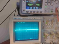
"layout" at the moment is horrible, yet still super reg keeps a square wave form 0.1 to 3.0 A at below 400uV, and in static measurement it is stable till 0,0001V at 0-5A draw. I hope that a really really tight PCB packed with small 0805 smd will be better.
Second question, what is your take on Susumu RG vs Vishay MELF in feedback path? I thought about using the multiple resistor in series as from Bob Cordell, to both minimize dissipation as well as voltage drop, and thus minimize both TCR and VCR. LTSpice agrees with <125mW in my project on all resistors when used in series. How about inductance ? Wouldn`t it be better to use carbon composition with non magnetic leads ?
"layout" at the moment is horrible, yet still super reg keeps a square wave form 0.1 to 3.0 A at below 400uV, and in static measurement it is stable till 0,0001V at 0-5A draw. I hope that a really really tight PCB packed with small 0805 smd will be better.
Attachments
Last edited:
- Home
- The diyAudio Store
- Super Regulator