Thanks for your suggestion. I'd looked at the caps but resisted doing it as I couldn't imagine any failure mode that would give those results. Your prompt motivated me to get that doubt out of the way. I changed them tonight and while it didn't get the circuit working at least that's another thing off the list.
Following that, looking for clues I measured resistances from the opamp pins to Vin. Getting some low numbers , I thought maybe I'd found a trail to follow until I remembered (UhOh!) the leads for bench supply and load were still connected. Pulling the supply connection put all pins up into the ≥300K range so no fish to fry there.
It could be that the thing to do is to strip down the board and start fresh. I don't like the idea much as I've replaced most of the parts once already.
Any suggestions for testing / circuit values to look for would be greatly appreciated.
In the meantime, I read earlier in the thread, Jan telling somebody they could use the negative reg for a positive circuit, just connecting appropriately. I'll try that.
Thanks again.
One more time: Any suggestions for testing / circuit values to look for would be greatly appreciated.
I would be willing to help but the thread is so long now it is very hard to know what the latest problem circuit is, and what the problem is.
Jan
Jan
Hi Jan,
Thanks for offering your help.
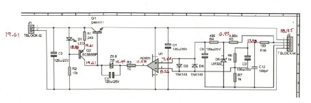
Of two full boards , two pos. and two neg. One positive reg (marked Jung/Didden pos superreg diyAudio v2.3b^R6) (stuffed with values from published BOM and using AD817) was started up for initial test with resistor load and powered by bench supply that had loose connection at the +V clip-lead to board. When moved this caused a spark . I don't know if this was the source of trouble or not but LED winked and then winked again when I re-checked the lead . After that, the LED circuit was inactive.
All parts on the board have been replaced except the resistors (which measure fine) and voltages remain the same with LED not lighting at all.
Load resistor is 330Ω plugged directly to screw terminal at the board output with 3cm length sense wires right there too.
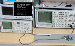
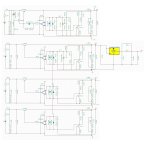
The voltages are posted on image.
Thanks for offering your help.
Of two full boards , two pos. and two neg. One positive reg (marked Jung/Didden pos superreg diyAudio v2.3b^R6) (stuffed with values from published BOM and using AD817) was started up for initial test with resistor load and powered by bench supply that had loose connection at the +V clip-lead to board. When moved this caused a spark . I don't know if this was the source of trouble or not but LED winked and then winked again when I re-checked the lead . After that, the LED circuit was inactive.
All parts on the board have been replaced except the resistors (which measure fine) and voltages remain the same with LED not lighting at all.
Load resistor is 330Ω plugged directly to screw terminal at the board output with 3cm length sense wires right there too.
The voltages are posted on image.
Attachments
Hello Jan,
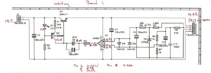
Re-posting the reply to your post as I didn't think to include the voltages from the working board in the post above this one, so am putting both here for easy comparison along with edited previous text to keep it all together.
Of two full bipolar boards built, all 4 circuits were populated with parts from the published BOM. Opamp is AD817.
Of the four, one positive and both negative circuits work as expected.
The one non-functioning positive reg (marked "Jung/Didden pos superreg diyAudio v2.3b^R6") was started up for initial test with resistor load and powered by bench supply that had loose connection at the +V clip-lead to board. When moved this caused a spark . I don't know if this was the source of trouble or not but LED winked and then winked again when I re-checked the lead . After that, the LED circuit was inactive.
All parts on the board have been replaced except the resistors (which measure fine) and voltages remain the same with LED not lighting at all.
Load resistor is 330Ω plugged directly to screw terminal at the board output with 3cm length sense wires right there too.
The voltages are posted on images.
Before I remove all parts and start again I'm hoping the voltages will let you tell me where to look.
Thanks again !
Attachments
The very last thing you want to do is replace parts at random - surely a smarter method is possible.
You did some good measurements on the bad board, that's useful.
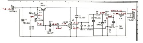
What I see is that the opamp inputs are such that the output should be low, but it isn't.
(Verify that the opamp input & output measurements are as shown for a double check to avoid chasing a ghost).
The opamp is trying to lower the voltage but it can't it is drawing the max current of 88mA.
Where is that 88mA coming from?
Not from Q2 because then it would also have to flow through R1 which is actually carrying zero current (same voltage on both sides).
The LED has 0.73V so unlikely it carries 88mA. What remains is Q1 - its Vc = Vb so looks like a C-B short.
Replace Q1 and verify.
Or better yet, first remove Q1 then verify the opamp no longer takes so much current, then put in a new Q1.
Let us know.
Jan
You did some good measurements on the bad board, that's useful.
What I see is that the opamp inputs are such that the output should be low, but it isn't.
(Verify that the opamp input & output measurements are as shown for a double check to avoid chasing a ghost).
The opamp is trying to lower the voltage but it can't it is drawing the max current of 88mA.
Where is that 88mA coming from?
Not from Q2 because then it would also have to flow through R1 which is actually carrying zero current (same voltage on both sides).
The LED has 0.73V so unlikely it carries 88mA. What remains is Q1 - its Vc = Vb so looks like a C-B short.
Replace Q1 and verify.
Or better yet, first remove Q1 then verify the opamp no longer takes so much current, then put in a new Q1.
Let us know.
Jan
Hi Jan,
Q1 was the first part I'd replaced and then the others. At that time, the pulled D44 tested good (on a Peak atlas) so figured I'd move on and test out other thoughts. (not random but systematically, according to limited understanding : )
Anyway, tonight you're the lucky charm, getting me back to the bench and pulling Q1 again, LED light bright and cheery. Replaced Q1 and circuit regulating at 14.5V. 👍🏼
I put the freshly pulled D44 back on the tester and it tests ok. I don't know how I missed a solder bridge twice but I guess I must have.
At any rate, hats off to you Jan. Your analysis was good teaching. I'd got stuck scratching my head on the ≈.7 drop at Q2 base to emitter and couldn't understand it. I was thinking the cause of circuit troubles was that Q2 wasn't conducting - not that something at the position of Q1 was.
Not being comfortable around opamps yet, I would never have run the circuit minus a part without your prompt either. Learning lots from this. Thanks there too.
Last edited:
It is possible for a transistor to test good but still fail in a circuit.
The tester (the simple ones like the Peak) test with small current, so that's not really representative for actual circuit it is used in.
Let me put it this way: if the tester say it is toast, it is toast.
If the tester say it is good, it still may be toast.
The other tinhg with opamp circuits is aleays to look at the input signals and see if the output seems OK.
For instance, in this case, the -input was higher than the +input so you expect the opamp to have very low Vo.
It wasn't, but you can see it is trying very hard, slurping up the max current it can.
So the opamp, the reference and output feedback all seem OK.
You work backward from that.
Jan
It's a small detail maybe but I really appreciated the sanity of your board organization. It made the build a notable pleasure. Thanks.
Board organisation is an important part of PCB layout.
You can easily recognized newbee designs by just looking at the board.
But it already starts at drawing the circuit.
If you organise that logically, you're halfway to a good PCB.
Jan
You can easily recognized newbee designs by just looking at the board.
But it already starts at drawing the circuit.
If you organise that logically, you're halfway to a good PCB.
Jan
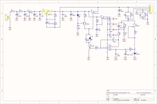
Today I measured the noise of my Jung/Didden super regulator which I use to power the muses72320 chip (+/-16V) in my ugs muse preamplifier.
I've just added additional filtering. I attach the schematics and files if anyone wants to use them.
Average RMS noise floor in audioband: ~540nV
I've just added additional filtering. I attach the schematics and files if anyone wants to use them.
Average RMS noise floor in audioband: ~540nV
Attachments
How is that you have such low noise with an opamp that has input voltage noise 12 nV/√Hz?Average RMS noise floor in audioband: ~540nV
In ideal case, output noise in 25 kHz bandwidth couldn’t be less than 2 uV. Can you verify measurement setup and confirm value?

I did this regulator 10 years ago. I probably used the original scheme from 1995.Why do you supply the opamp from the unregulated voltage?
But you're right. I will fix the circuit board. Thank you !
I will do the tests again tomorrow.How is that you have such low noise with an opamp that has input voltage noise 12 nV/√Hz?
In ideal case, output noise in 25 kHz bandwidth couldn’t be less than 2 uV. Can you verify measurement setup and confirm value?
With average function and without average. And will do video.
Attachments
Last edited:
There is no use from YouTube video at all.
Just verify your measurement equipment calibration. Even resistor as a calibration source is enough. Connect your noise measurement setup probes to 1500 Ohm resistor and measure noise. Averaged value for 25 kHz bandwidth should be some 780 nV. If so, then you can repeat regulator noise measurement.
Just verify your measurement equipment calibration. Even resistor as a calibration source is enough. Connect your noise measurement setup probes to 1500 Ohm resistor and measure noise. Averaged value for 25 kHz bandwidth should be some 780 nV. If so, then you can repeat regulator noise measurement.
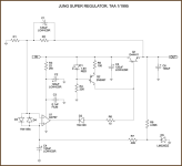
I see that Per Anders in his SJÖSTRÖM SUPER REGULATOR for 5V also supply the opamp from the unregulated supply.
But from 12V and up - from the regulated ones.
Тhere's probably a reason for that. Maybe startup problems.
(I'm showing part of the schematics with values deleted because I paid for the all his schematics years ago and I'm not allowed to post them without his permission.)
But from 12V and up - from the regulated ones.
Тhere's probably a reason for that. Maybe startup problems.
(I'm showing part of the schematics with values deleted because I paid for the all his schematics years ago and I'm not allowed to post them without his permission.)
Attachments
The AD825 cannot work with a 5V power supply. For this reason SJÖSTRÖM SUPER REGULATOR uses an unregulated power source for AD825 if the output voltage is lower than 12V.
The only jfet op amp that works with 5V is the ADA4625 but then it has to have a 1V reference instead of 2.5V.
The only jfet op amp that works with 5V is the ADA4625 but then it has to have a 1V reference instead of 2.5V.
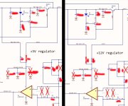
Gromcat, powering opamp from an external supply will directly affect psrr, snr and other things and the end result would be not what you expect from j.d. regulator! But you can do things easy using an 15V j.d. as a power source for all other opamps, even 1.8V j.d. regulator is posible that way. Also you can share ref voltage to other reguloators. This is an old simulation, fb must be before 680nH otherwise output voltage noise happening. Also J113 must be removed for 5V and <5V reg and used simple resistor divider. This is an example.
Attachments
Last edited:
- Home
- The diyAudio Store
- Super Regulator