It really makes no sense to make a shunt regulator for 5V / 2A because of the excessive dissipation, which would be at least 10W and more. The problem is the voltage drop on the depletion mosfets, which will certainly be higher than 5V.@grunf What would be good available replacement part for 2SK246, 2SK35577 and can I use it with your JLH69 version regulator this also? Also I like to add your JLH69 version this input CCS with right parts to get 5V and 2A out.
https://www.diyaudio.com/community/threads/walt-jung-shunt-design.383690/post-7016961View attachment 1229126
grunf another version of JLH69 regulator
View attachment 1229133
I have built this following grunf JLH69 version ( on the 3rd picture) using Q1,2 - DB140 and 2SC2500. 5V out and using it to power soundcard consumption with 1.5 amps. Can I just add J1 and Q3, Q4 from upper schematic to this my built one to improve this regulator further more? I also like to add this CCS that was used in the first picture using right parts to this schematic what I have built. I really need help and guidance for that.
View attachment 1229136
Thank you!
I assume that it is a regulator for a DAC or something similar so it would be better to make more regulators for smaller currents and power each load separately. Let's say for 5V/ 130mA a 4-5V voltage drop is enough and the dissipation will be small around 1W.
I hope that for the 5V version you don't use the AD825 as an op amp, an excellent choice is the ADA4897 if you know how to 'tame' it but for a start the AD817 will be great.
You can freely use J1, Q3 and Q4 instead of LM329 and R4, but for 5V you have to remove D9, D8 and D7. Instead of J1, you can also use CCS with two depletion mosfets from your first picture with two BSS139 set to a current of ~5mA.

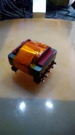
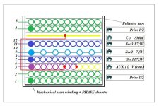
Some work in relation to my post 3367, transformer was not done right, it emited some noise and now it contain common mode cancelation trought aux -> shield winding. Also pcb have some modifications on booth sides, now gnd layer is canaled to force current trought inline dc filter capacitors. I will let you know the final result.
Attachments
![DSC_2226[1].jpg](/community/data/attachments/1147/1147715-534eb9e15daa887ca867d713417598e0.jpg?hash=U0654V2qiH)
![DSC_2227[1].jpg](/community/data/attachments/1147/1147716-64f773f3adca9ccddc737535f2518b34.jpg?hash=ZPdz863KnM)
Tried to purchase BC556 and companion no luck yet
What substitute for this pair can do the trick?
What substitute for this pair can do the trick?
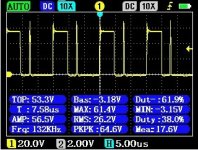
In relation to post 3382, some result. J.d. regulators are so sensitive to emi noise that they must not be close to flyback regulators, j.d. it picks up the emi noise and through its output we get this kind of spike on the flyback regulator itself, I've been working on solving the problem on flyback for several days and I barely managed to figure out what it was about, its not a problem of flyback but problem of emi : ) I had noise at the j.d. out and in the same time spike inside flyback Ton time. I hope that when I split this board in half and move one away from the other that it will finally everything falls into place. Please take a look at two pictures, one is at mosfets Ton on flyback and seccond one is noise I had on mini j.d. More results soon : )
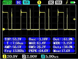
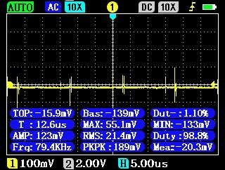
only when I put these two pictures one under the other, I figured out what the problem was, emi! Unbelievable is that j.d. puts spike back to the flyback because of emi pickup from the switching noise : )
only when I put these two pictures one under the other, I figured out what the problem was, emi! Unbelievable is that j.d. puts spike back to the flyback because of emi pickup from the switching noise : )
Attachments

Last edited:
In the original 1995 articles, Walt Jung used 2N5087 etcTried to purchase BC556 and companion no luck yet
What substitute for this pair can do the trick?
Found a store that has both BC556b and BC546b, but not from the same manufacturer though. One is from On Semi the other from Vishay. Might not matter but I don't like that fact. Hfe is indicated as 150 on both.
Will these work?
Will these work?
Its a matter of insecurity management. Suppose the devices from the two different manufacturers are not the same, despite the same data sheet.
But you don't know which of the two is 'better'. By deciding for one or the other, you may get the 'worse' of the two.
Better to buy from different manufacturers then at least you have 50% the best. 😎
Just pulling your leg a bit. Don't worry, they are totally uncritical because of the heavy internal feedback in the circuitry.
Jan
Thanks Jan appreciate it.
For those of us that have no electronic background it would help if the BOM had two more rows with easy to purchase current substitute parts.
For those of us that have no electronic background it would help if the BOM had two more rows with easy to purchase current substitute parts.
That's a tall order - how do we know what's obsolete and what is available and where, a couple of years from now? It's very dynamic.
There's no substitute to building up personal experience, check data sheets and ask around.
It's not different from what I would do.
Jan
There's no substitute to building up personal experience, check data sheets and ask around.
It's not different from what I would do.
Jan
@juliobozek Thank you for asking about Kevin Gilmore golden reference low voltage power supply. I had same question and I recently found out about this schematic. I really like to see new improved super regulator. I do not have any background to engineer one for myself. I just feel and hear the difference and I love music that flows and enlightens me. I have seen many improvement ideas put not a full schematic that takes them all a count.
@jan.didden Any plan to update this super regulator and PCB-s in Diyaudio store? I really love to see that. It could be 2 versions one for lower amps and a upgrade to up to like 2 amps version using the same PCB.
@grunf What would be good available replacement part for 2SK246, 2SK35577 and can I use it with your JLH69 version regulator this also? Also I like to add your JLH69 version this input CCS with right parts to get 5V and 2A out.
https://www.diyaudio.com/community/threads/walt-jung-shunt-design.383690/post-7016961View attachment 1229126
grunf another version of JLH69 regulator
View attachment 1229133
I have built this following grunf JLH69 version ( on the 3rd picture) using Q1,2 - DB140 and 2SC2500. 5V out and using it to power soundcard consumption with 1.5 amps. Can I just add J1 and Q3, Q4 from upper schematic to this my built one to improve this regulator further more? I also like to add this CCS that was used in the first picture using right parts to this schematic what I have built. I really need help and guidance for that.
View attachment 1229136
Thank you!
Just wondering if in picture 2 instead of Q3 and Q4 I can use BC850C and BC860C? Or maybe there is better SMD equivalents?
When I use OPA1611 as op amp in this regulator then I have output 5V but when I replace it with ADA4897 then the output is 3.6V. Can someone explain me that and how to increase the output to 5V?
Sorry I was not clear on that.That's a tall order - how do we know what's obsolete and what is available and where, a couple of years from now? It's very dynamic.
There's no substitute to building up personal experience, check data sheets and ask around.
It's not different from what I would do.
Jan
I do not suggest that the designer/s need/s to update the BOM.
If first post had the BOM with two or three more columns then those experienced in the art could fill in what substitute worked for them.
I don't mind comparing data sheets but I certainly don't have the knowledge to know what specs are the important ones in a specific design.
I don't know If the forum is technically able to provide fill in sheets but it would be a nice feature for any first page of a thread.
Just dreaming 😉
In the Walt Jung article from post #3331 2N3906 and PN2222A was used. So MMBT2222 and MMBT3906 as SMD should be ok. I want to make GLED431 voltage reference 6.9V for +15V and -15V regulator. For CCS probably BSS169 will be ok?Just wondering if in picture 2 instead of Q3 and Q4 I can use BC850C and BC860C? Or maybe there is better SMD equivalents?
View attachment 1243548
Do you have a schematic?When I use OPA1611 as op amp in this regulator then I have output 5V but when I replace it with ADA4897 then the output is 3.6V. Can someone explain me that and how to increase the output to 5V?
I have never had a problem with the ADA4897 in 5V or 3,3V regulators .
For the normal version it will be OK for the high current version it will not, in that case they must have at least 1W of dissipation. BSS159 will be better than BSS169 but it can also be used.In the Walt Jung article from post #3331 2N3906 and PN2222A was used. So MMBT2222 and MMBT3906 as SMD should be ok. I want to make GLED431 voltage reference 6.9V for +15V and -15V regulator. For CCS probably BSS169 will be ok?
- Home
- The diyAudio Store
- Super Regulator