Hello. Just stuffing a board and have a question about Q1. I have the 60 Volt D44H8 version of the D44H11 (which is 80V). Just wondering if there are expected high transients or whether the lower limit value is ok. I expect to be using the supply for 15V (and no higher than 25V).
Thanks
Thanks

For +5V Super Reg - Use one LED for D2 with Anode toward the op amp and for -5V Cathode toward the op amp.Does it work -5v ? I will use +5v -5v on my pcm56 dac.
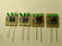
In the simulation, 5v worked with a 2.4v zener diode. Some people in the forum said that two series LEDs instead of a zener diode for 5V are better and noiseless? What is your opinion on this?
You can use 6.8 Ref for D5 - for 18V outputI started reading the super regulator discussions from the first page, I am now on page 40.
My simulation could not simulate for 5volt and 3.3Volt with 6,8V zener. When I learnt that a few people in the forum made the 5volt application with two series LEDs, I simulated in this way. "I would like to point out that the 6V8 zener 12V 15V 18V worked in the simulation."
I will continue my way with AD817. Because the voltages I want are 5V 12V 12V 15V 18V. I gave the components orders, I will order the pcb after real-time tests.
Finally, as you mentioned in your article, should we use a 7.5v or 8.2v zener for the output voltage after 15v, for example 18v?
Thanks for your understanding and patience @jan.didden
Maybe it is simulation fall. but I need to chance for R2 110 ohm instead 249 ohm, if ı use one led.For +5V Super Reg - Use one LED for D2 with Anode toward the op amp and for -5V Cathode toward the op amp.
Attachments
Hmm, its interesting that when led is instead of zener noise is ten times less than with zener. What I have noticed in simulation using zener PSRR is a bit better and smother using zener but not much diferent than with using led, fine tuning in schematic is needed, definitelly using led is beter than zener. Looks realy promising! Tried simulation using 2V led. In next discrete j.d. I will definitely replace zener with led. : ) Jan what is your opinion?
Last edited:
I wouldn't really bet that a zener is better than an LED, see my DAC, there isn't a single zener diode😉 .
btw ; for 5V regulators, I tested AD8091, AD817, LT6202 and ADA4897 and they all work great, ADA4897(or ADA4625 with 1V ref) is definitely the best.
btw ; for 5V regulators, I tested AD8091, AD817, LT6202 and ADA4897 and they all work great, ADA4897(or ADA4625 with 1V ref) is definitely the best.
Attachments

Attachments
Grunf, I don't know if this is relevant but TinaTi simulation shows that with zener psrr is much beter than using led, the rest of things is not much diferent. Bode plot is better too using zener. Mean about when single zener is replaced with single led. Otherwise TinaTi have a bug?
Attachments
Last edited:
You'll get even better PSRR when you replace the zener with a TL431 adjustable shunt reference IC (set for the same zener knee voltage). But TL431 is not characterized for noise performance.
3.3V regulator might be possible with GS8331 opamp, maybe even 1.8V? The 1V ref would be need e.g. REF35102, ISL60002... Opinions?
Last edited:
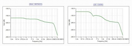
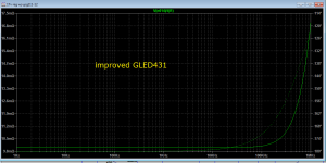
For comparison, these are the impedance of the classic zener BZX84B6V8L in a series regulator and the impedance of the improved GLED431 in the same regulator.Grunf, I don't know if this is relevant but TinaTi simulation shows that with zener psrr is much beter than using led, the rest of things is not much diferent. Bode plot is better too using zener. Mean about when single zener is replaced with single led. Otherwise TinaTi have a bug?
The difference is huge and affects the performance of the regulator a lot. In Walt's articles that I posted a few posts ago, you have measurements that accurately confirm these improvements.
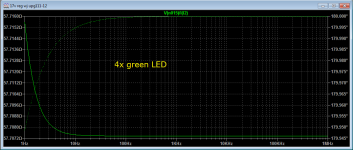
For comparison with your simulation, I put four green LEDs as a reference, the voltage is a little higher at 7.9V but the simulation exactly confirms yours. A standalone LED will be worse than a regular zener diode.
Attachments

Oven controled shared vref might be interesting? This https://it.aliexpress.com/item/1005003724394232.html also might be used e,g, for gled431
Attachments
Last edited:
Hello,
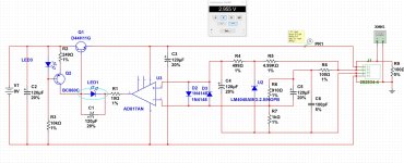
I built two complete boards , three circuits of which are working as expected. This one positive reg. circuit isn't .
When testing this one with bench supply, the connection was loose and when I moved the +V wire from the supply there was a visible spark at the board connector.
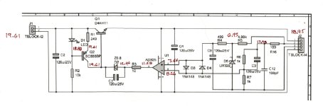
After securing the connection I powered the supply up and the regulator LED blinked but didn't stay on. After fixing the connection the LED would blink on for a few milliseconds then go off. This happened twice. Then on third power up, no light and voltages as shown on attached schematic.
Now I have changed all LED, PNP, NPN, vrefs, and the AD817 , checked resistors and reflowed all joints and still voltages stay as posted.
Would somebody please have a look at the scheme voltages and let me know if they spot anything obvious?
Thanks very much.
I built two complete boards , three circuits of which are working as expected. This one positive reg. circuit isn't .
When testing this one with bench supply, the connection was loose and when I moved the +V wire from the supply there was a visible spark at the board connector.
After securing the connection I powered the supply up and the regulator LED blinked but didn't stay on. After fixing the connection the LED would blink on for a few milliseconds then go off. This happened twice. Then on third power up, no light and voltages as shown on attached schematic.
Now I have changed all LED, PNP, NPN, vrefs, and the AD817 , checked resistors and reflowed all joints and still voltages stay as posted.
Would somebody please have a look at the scheme voltages and let me know if they spot anything obvious?
Thanks very much.
Attachments
My idea it is….Could you try more input voltage? Because it writes on pdf Vin must be high 5v from Vout
Hi and thanks. I did try that but at your post I just ran the input up to 24V again and still no go.
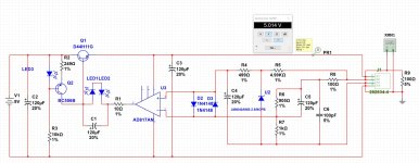
I do wonder about the voltages for the CCS and R2. On the working positive reg, - with 19.7V input , 14.52 regulated out), the drop across the LED is 2.41V . That works out to 0.24mA through R2 and there is 6mA through R3.
The voltage across the LED in the problem circuit is 0.73V, which looks like a diode drop but don't know its cause yet. Not sure if the full input voltage at both top and bottom of Q2 looked like it might be a short so I changed both BJTs and checked the board but voltages remained the same and no surface fault was found.
It's late here now. I'll take another look tomorrow night.
Thanks.
- Home
- The diyAudio Store
- Super Regulator