I am a beginner to circuit simulation and tried to simulate the Super Regulator in LTSplice.
I wanted to check the output voltage and its effects when changing the resistor value R6, based on the table below.

I am not sure if LTSplice can simulate the actual voltage at the output of the regulator or not, I am a beginner to circuit simulation and also unsure if the method I am following is the correct one.
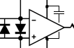
When I simulate in LTSpice with 18V DC as input voltage and load the output with a 1k resistive load the voltage measured in Vout is 16.61v and this value doesn't change with change in R6 value, in the below image R6 value is 639 ohms and as per the table approx Vout should be closeto 12V.
Reference voltage 6.9V
R7 - 1000 ohms
R16 - 100 ohms
R6 - 639 ohms
Desired output voltage 12V
Vout in simulation: 16.6v but this should be 12v not sure why I get 16.6 volts.

Here I have changed R6 to 1070 ohms and the output voltage of the circuit still remains 16.62volts.

Attached are LTSpice files which I have used and I got the files from this thread as well.
Any help with this will be helpful, may be there is something wrong I am missing .
Thanks in advance for your help and support.
I wanted to check the output voltage and its effects when changing the resistor value R6, based on the table below.
I am not sure if LTSplice can simulate the actual voltage at the output of the regulator or not, I am a beginner to circuit simulation and also unsure if the method I am following is the correct one.
When I simulate in LTSpice with 18V DC as input voltage and load the output with a 1k resistive load the voltage measured in Vout is 16.61v and this value doesn't change with change in R6 value, in the below image R6 value is 639 ohms and as per the table approx Vout should be closeto 12V.
Reference voltage 6.9V
R7 - 1000 ohms
R16 - 100 ohms
R6 - 639 ohms
Desired output voltage 12V
Vout in simulation: 16.6v but this should be 12v not sure why I get 16.6 volts.
Here I have changed R6 to 1070 ohms and the output voltage of the circuit still remains 16.62volts.
Attached are LTSpice files which I have used and I got the files from this thread as well.
Any help with this will be helpful, may be there is something wrong I am missing .
Thanks in advance for your help and support.
Attachments
Last edited:
Rick have those pulses been resolved?MY SR was set for 20V and I changed both D2, D7 and D5, D10 to 10V. Yes, D5 and D10 need to be the same, whatever they are. One is for positive rail, the other is for negative rail. You could safely use 12 volt in all 4 positions, it's half your output voltage.
Jan
No they have not. I have ordered some AD825's to replace the untested opamps I installed. I may actually have some NE5534's that I could try for now, that would allow me to keep my output at 18V. I'll have to lower to 17volt using the AD825's.Rick have those pulses been resolved?
Jan
If they remain with different opamps, also with (temporarlily) lower voltage, it's a pretty good bet that it is externally caused.
Just make sure you have enough headroom across the pass device, including the ripple valleys.
You can make sure of that by temporarily lowering Vout to 12V or so and use a light load, just for testing.
Scope the input if possible.
Jan
Just make sure you have enough headroom across the pass device, including the ripple valleys.
You can make sure of that by temporarily lowering Vout to 12V or so and use a light load, just for testing.
Scope the input if possible.
Jan
Have you ever seen any issues with providing the input VDC with a bench supply? I have been using a Rigol DP832 set at 25 volts for 18 volts out. I did scope the input and output and they were exactly the same except the input was inverted. I tested the power supply without the regulator attached and it is clean. I'll start with changing the opamps to a proven opamp, then go from there.
I've never seen something like that.
Don't you have another psu laying around to feed it, to exclude the bench supply as a source?
You just need a xformer, diodes and a cap, nothing fancy.
Output voltage not critical either, as long as it is high enough for the Vout (which can be temporary lowered also for diagnosing purposes).
Jan
Don't you have another psu laying around to feed it, to exclude the bench supply as a source?
You just need a xformer, diodes and a cap, nothing fancy.
Output voltage not critical either, as long as it is high enough for the Vout (which can be temporary lowered also for diagnosing purposes).
Jan
I'm working on that and will let you know after I test with that. I did change one rail to NE5534 and the pulses are way lower but still there. I'm suspecting some interaction between the bench supply and the board.
I have fixed this the problem was with the lib model loaded took me some time to figure it out .I am a beginner to circuit simulation and tried to simulate the Super Regulator in LTSplice.
I wanted to check the output voltage and its effects when changing the resistor value R6, based on the table below.
View attachment 1125912
I am not sure if LTSplice can simulate the actual voltage at the output of the regulator or not, I am a beginner to circuit simulation and also unsure if the method I am following is the correct one.
When I simulate in LTSpice with 18V DC as input voltage and load the output with a 1k resistive load the voltage measured in Vout is 16.61v and this value doesn't change with change in R6 value, in the below image R6 value is 639 ohms and as per the table approx Vout should be closeto 12V.
Reference voltage 6.9V
R7 - 1000 ohms
R16 - 100 ohms
R6 - 639 ohms
Desired output voltage 12V
Vout in simulation: 16.6v but this should be 12v not sure why I get 16.6 volts.
View attachment 1125913
Here I have changed R6 to 1070 ohms and the output voltage of the circuit still remains 16.62volts.
View attachment 1125914
Attached are LTSpice files which I have used and I got the files from this thread as well.
Any help with this will be helpful, may be there is something wrong I am missing .
Thanks in advance for your help and support.
Thank you.
18VDC out.
Positive rail only.
NE5534 installed.
Powered with a linear CRC power supply with 26VDC going into the input.
2.2k resistor for load, (9mA)
I measured 7.77VDC across the pass transistor.


Positive rail only.
NE5534 installed.
Powered with a linear CRC power supply with 26VDC going into the input.
2.2k resistor for load, (9mA)
I measured 7.77VDC across the pass transistor.
When I added a second 2.2k resistor in parallel the vVpp on the scope display went up to about 170mV. When this picture was taken the Vpp was low, it usually rides around 140mV.
18V out.
Negative rail only.
AD825 installed.
10V zener installed in D7 position.
LM4040-10 installed in D10 position.
Nichicon FC 100uF caps used for C5, C6, C7, C8, C10.
BC546B in Q4 position.
D45H11 in Q3 position.
R14 1k.
R13 698R.
Everything else as listed.
Powered with a Rigol DP832, 25 volts.
2.2k resistor for load, (9mA)
I double checked every resistor, diode, and other component.
This won't quit oscillating.
Positive rail exactly the same at 38kHz. Has anyone ever checked the output of one of these with an oscilloscope?
Yes, I have examined both the boards from the original Old Colony boards (1995 Audio Amateur) articles and those offered by DIYAUDIO and have observed no similar excitation.Positive rail exactly the same at 38kHz. Has anyone ever checked the output of one of these with an oscilloscope?
Yes, from Mouser, did the same thing with NE5534 and OPA828 on both rails.Genuine AD825 op amp?
The only other thing significantly different is the LM329 was replaced with a 10V reference, the LM4040-10, along with the zener on the opamps output was changed to 10V. I have read other people have used the FC caps, the one picture in the writeup I believe shows FC caps. Any ideas?
I think I'm going to change back to a 6.9V reference using the LM329. The way I'm looking at this, everything on the output is exactly as shown in the BOM and schematic. the issue has to be on the opamps input side, I think. I did just look up the noise of the LM4040-10 and its 180uV compared to 7uV on the LM329. That extra noise could some how be creating an oscillation on the input.
Hi, Just to be sure that may help :I think I'm going to change back to a 6.9V reference using the LM329. The way I'm looking at this, everything on the output is exactly as shown in the BOM and schematic. the issue has to be on the opamps input side, I think. I did just look up the noise of the LM4040-10 and its 180uV compared to 7uV on the LM329. That extra noise could some how be creating an oscillation on the input.
- Put a 10nF across the Positive and Negative pins of the AD825... (I had the problem with HV regulators in my 6C33C-B amp.)
Attachments
- Home
- The diyAudio Store
- Super Regulator