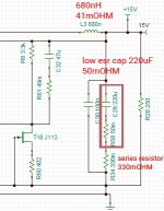
My mistake. yes its series resistor to low esr caps at the input and output. Simulation tells that optimum esr cap need to be around 350mOHM + L=2.2uH, is this ok?
Yes ESR is goed, not sure abourt the L. Seems high to me, but I have never researched it TBH.
Jan
Jan
I'm going to build the superreg for my Pass Pearl II phono preamp (1 for each channel). + and - 24V. I read the whole thread, this answered most of my questions. I will try the OPA1611 as it seems to measure very well and was stable in other builds. For the output cap I selected TDK/Epcos b41888 series 100 uF 50V with a Z of 540 mOhm at 1Mhz. I do have a question about the C and R for the sense line. Stock values are 100 Ohm, 100 pF. Somewhere in the thread it was suggested that 10 Ohm and 0,01 uF would be better (lower resistance at high frequencies). Is it better to go with the alternative values, or should I just stay with the stock values? Second question is about the power dissipation of the pass transistor. I have about 33V coming in and 100mA per rail, so that would be 0.9W. Is there more (idle) dissipation that I should take into account when choosing the heatsink?
I don't know about 'lower resistance at high frequencies' - the purpose is to roll off the feedback at hf to prevent instability due to lengthy sense wires.
10R and 10nF might work, you could try it.
For the dissipation, there's no additional dissipation in the reg itself to speak of, so your 0.9W seems correct.
Jan
10R and 10nF might work, you could try it.
For the dissipation, there's no additional dissipation in the reg itself to speak of, so your 0.9W seems correct.
Jan
Thanks for your answer. I was referring to some posts by Walt Jung (#819 and 836). As I'm not really an electronics expert I thought I'd ask. Can't find the post about resistance. Maybe meant value of the resistor + reactance of the capacitor, which indeed is higher for 100R+100pF. But I don't know if that's desirable in this spot or not. There was also a post by someone who accidentally installed a 100 nF instead of 100 pF, which resulted in oscillation.
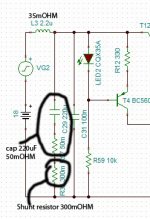
I have done things diferently, instead of resistor divider I added fet, and fb is connected at the star between coil and cap, it improved things a lot, would be happy if somebody confirm improvement. Also as Didden told there should be no low esr cap at the out, instead I have added some series resistance, see picture. I'm using NE5534
Attachments
Last edited:
I recently found a bunch of pcb's in a drawer 😎, Jung/Didden version 2.2
Will the boom for v2.3 work for these just as well ? Any other changes ?
Will the boom for v2.3 work for these just as well ? Any other changes ?
Can I keep R5/12 at 4k99 for a 24V version with the LM329? That would mean around 4.8 mA through the LM329 in stead of the 2 mA I read somewhere in this thread was the value to aim for (though not critical)? If I change the value of R5/12, should R4/11 also be changed?
You can inrease R5/12 to lower the current to save a bit, but not necessary.
R4/11 can stay anyway.
A quick look at the data sheet shows dynamic impedance pretty flat with current.
Noise spec is not given re: current, so assume it is also flat with current, and is filtered anyway.
Jan
R4/11 can stay anyway.
A quick look at the data sheet shows dynamic impedance pretty flat with current.
Noise spec is not given re: current, so assume it is also flat with current, and is filtered anyway.
Jan
Attachments

Well, I've finished building my first superreg:

voltage divider resistors still mounted provisionally. Voltage is within a hair of the theoretical value given the Vref and resistor values at 23,98 V and -23,97 V (loaded with a 1k resistor as shown). Opamp is the OPA1611.
When I put the probe of my scope on the output of the reg ( + or - leg of the 1k resistor, ground clamp of the probe to the return leg of the resistor) I'm seeing some strange pulses. Similar on the pos and the neg regulator. They also show up when I measure a 7809, so it might just be some interference the scope picks up? I'm not really an expert here.

(2mV/div and 10mS/div)
voltage divider resistors still mounted provisionally. Voltage is within a hair of the theoretical value given the Vref and resistor values at 23,98 V and -23,97 V (loaded with a 1k resistor as shown). Opamp is the OPA1611.
When I put the probe of my scope on the output of the reg ( + or - leg of the 1k resistor, ground clamp of the probe to the return leg of the resistor) I'm seeing some strange pulses. Similar on the pos and the neg regulator. They also show up when I measure a 7809, so it might just be some interference the scope picks up? I'm not really an expert here.
(2mV/div and 10mS/div)
a nice flat line (less noisy than between the pulses of the super reg). Unconnected the tip picks up some faint 50Hz sine wave
OK, so if you now connect the scope ground and tip, still connected, to the superreg ground, switched on?
Jan
Jan
Just to add: the 7809 was connected to an old 13.8V linear supply, the superreg is connected to the PSU from my phono preamp (toroid 2x22V, CRCRC filter after rectification) which has about +/- 33V output.
Just a bit of noise, see below. Probe disconnected from ground now shows the same.

I'm in a different room now. Maybe interference from some household appliance? Dishwasher was running earlier on (though it has its dedicated group)
I'm in a different room now. Maybe interference from some household appliance? Dishwasher was running earlier on (though it has its dedicated group)

- Home
- The diyAudio Store
- Super Regulator