That would work, you'd have to check the output noise but that's filtered anyway.
Note that you can't use ta 10V ref for a 5V reg; the output voltage cannot be lower than the ref voltage (using the diyaudio pcb).
Jan
Note that you can't use ta 10V ref for a 5V reg; the output voltage cannot be lower than the ref voltage (using the diyaudio pcb).
Jan
Jan, yes, I understand the voltages, but I didn't get what exactly the noise concern is. Could you please elaborate? Thank you!That would work, you'd have to check the output noise but that's filtered anyway.
Jan, am I wrong or some time ago, last year or before, there was a discussion on the OPA140, which seemed very promising and then it didn't prove to be so? I mean for the super regulator.
I remember there was no LTSpice model available and adapting the Spice model proved tricky or something.
I was interested in it too for using as RIAA preamp opamp, having input FETs, and I had to get some help to adapt the Spice model.
But the opamp didn't perform particularly well on the simulation. I any case I was planning to get some to try them with adapters.
I don't remember that, and I haven't used it myself.
Studying the datasheet it looks like a good candidate for the superreg.
Would be nice if you gave it a try and report here what you find.
Jan
Studying the datasheet it looks like a good candidate for the superreg.
Would be nice if you gave it a try and report here what you find.
Jan
Of course. All my audio projects have been in stand-by since the pandemic.
And it's probably time I start waking them up.
And it's probably time I start waking them up.
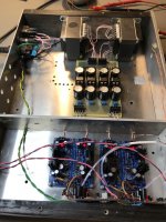
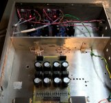
A properly implemented superreg is no joke. This is the best SQ I've achieved yet in my room. Stumbled out of the gate with my first attempt due to my own lack of attention, and awarded with oscillation. This is my 4X gain discrete opamp (BA 2018) with the alternate beefy output transistor option, able to drive headphones, autoformer, etc. Dual bobbin xformers, raw DC supply with 47mH CMC's between some type 3 Nichicon UKZ's in a Pi filter arrangement. Reg's have WJ's improved voltage ref update, AD825 op amps.
Attachments

Interesting.
I'm trying to plan my way through a very similar setup.
A couple of questions:
How did you arrange your grounding? You seem to be isolating supply and return for each transformer secondary through separate regulators to the preamp board. Are the signal grounds isolated from the shield? Is there a "star"?
More importantly for this thread... where did you attach the sense wires to the preamp circuit? Did you try various points?
Thanks.
A properly implemented superreg is no joke.
Hi William and congrats on your build, super impressive! I use a +5V SR as a USB power for my DAC, Aqua La Scala (balanced PCM1704K, frame-grid Telefunken ECC801S) and the sound quality is stunning compared to anything else I've tried.
I am also planning to build a +/-18V SR for my phono preamp, Rega Aria, as well as for other parts of my stereo. So I wonder if you'd be willing to help by sharing some of your experiences and details of your build. I use a 13V 16AH LiFePO4 battery at the moment, but your choke rectifier looks great. I wonder if you could please post the schematics and the list of parts you use, including the upgraded parts in the SR.
Are you saying that the discrete opamp did not work and was oscillating, but AD825 work fine? I also use AD825 (powered by 5V twice lower the specs), but I want to try other options. Also, what are the boards at the very bottom of the photo?
Thanks so much,
Alex
Yes that's right. Isolated all the way through finally meeting at the client (load). The wiring gets very "busy" at the load where it all comes together. Connection diagrams are shown in the old Audio Amateur "Regs for High Performance Audio" articles. On the sense wire I used Mogami 2552 (I think, or 2549? can't remember). With the shield connected only on the regulator side. Sense wires connected at exactly the same point as the load wires on the client. Didn't try anywhere else.Interesting.
I'm trying to plan my way through a very similar setup.
A couple of questions:
How did you arrange your grounding? You seem to be isolating supply and return for each transformer secondary through separate regulators to the preamp board. Are the signal grounds isolated from the shield? Is there a "star"?
More importantly for this thread... where did you attach the sense wires to the preamp circuit? Did you try various points?
Thanks.
Thanks.
I take it your power supply was inspired by Gary Galo's featured in those articles?
I was going to use that as inspiration as well.
Good build.
I take it your power supply was inspired by Gary Galo's featured in those articles?
I was going to use that as inspiration as well.
Good build.
Hi Alex. I'm not a phono guy and have no experience in that realm. But I suspect the PS needs to be really good, and quite possibly you would want the raw DC portion in a separate enclosure connected with an umbilical.Hi William and congrats on your build, super impressive! I use a +5V SR as a USB power for my DAC, Aqua La Scala (balanced PCM1704K, frame-grid Telefunken ECC801S) and the sound quality is stunning compared to anything else I've tried.
I am also planning to build a +/-18V SR for my phono preamp, Rega Aria, as well as for other parts of my stereo. So I wonder if you'd be willing to help by sharing some of your experiences and details of your build. I use a 13V 16AH LiFePO4 battery at the moment, but your choke rectifier looks great. I wonder if you could please post the schematics and the list of parts you use, including the upgraded parts in the SR.
Are you saying that the discrete opamp did not work and was oscillating, but AD825 work fine? I also use AD825 (powered by 5V twice lower the specs), but I want to try other options. Also, what are the boards at the very bottom of the photo?
Thanks so much,
Alex
Walt talks about the SR tweak here: https://refsnregs.waltjung.org/An_Improved_Reference_Filter_for_Audio_Regulators.pdf
I liked Gary Galo's approach in his old articles with the dual bobbin transformers and CMC's with a line level project. Regarding attenuation of high frequency junk riding on the mains. Caps: LKG1V102MESZCK, B32529C1474J289 CMC: SSR21NV-M10475 Transformers: A41-80-36. Bridge rectifier diodes are 11DQ10's.
My discrete opamp had .1uF film cap decouplers on the rails, SR did not like that one bit! My own fault for thinking I could get away with it... laziness mainly
Purple boards are the gain stage, given out at Burning Amp 2018 by Wayne Colburn.
Attachments

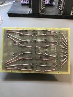
Yes, that's the way it should be done.Yes that's right. Isolated all the way through finally meeting at the client (load). The wiring gets very "busy" at the load where it all comes together. Connection diagrams are shown in the old Audio Amateur "Regs for High Performance Audio" articles. On the sense wire I used Mogami 2552 (I think, or 2549? can't remember). With the shield connected only on the regulator side. Sense wires connected at exactly the same point as the load wires on the client. Didn't try anywhere else.
Good job.
Jan
Way back in the 90s Jan wrote that some crazy person would put Super Regs in each stage of the circuit with each active component driven individually by an individual Super Reg.
Well if we count op amps as an active device this is what I ended up doing. I used the Muffsy MC head amp and drove that with its own Super Reg. For the phono stage I used a Bugle 2 that uses 3 op amps. Here the PCB that was designed by Jim Hagerman used RC filtering progressively to each of three op amps so that each successive one would be more filtered. I was able to reach and separate each op amp individually!
Initially the RIAA stage was only powered by one Super Reg with no remote sense. Each op amp was fed directly from the SuperReg. Then I added two more Super Regs and used remote sense for each op amp. Call me crazy but there was a distinct improvement in dynamics and resolution. when remote sense was installed to each individual op amp.
Finally my vinyl sounds as good as my Topping D90SE DAC. They are different but each sounds as good as the other depending on individual recording.
This is my final phono stage. Overkill? Maybe but it was fun.
I used a dual LT1083 as a prereg before the SuperRegs. The transformer was retrieved when I dismantled my AD744/811 preamp from the 90s and that also sported a SuperReg. I used AD825s to power the SuperRegs. Jan is right with the remote sense lines, the preamp has a lot of wires emanating from it. Fortunately the Bugle PCB has a ground plane so removing the masking layer allowed easy grounding points.
https://www.muffsy.com/build-the-muffsy-mc-head-amp-mh-1
https://hagerman-audio-labs.myshopify.com/products/bugle2
That is a very ambitious setup!
At least you do no longer have to worry about the power supply quality! Well done.
Jan
At least you do no longer have to worry about the power supply quality! Well done.
Jan
I'm evaluating the super reg as an upgrade to the Hafler 9500 AFE PS. The dc supply off the rectifier is filtered with 1000uf /.1uf caps before the LM 317/LM337 (and their resistors etc.) regulators followed by some additional 100uf caps and diodes to ground. Despite the electro-mechanical aspects of this project, I would appreciate some input as to the topology. Can I eliminate all of the existing filter caps? My understanding is that this afe is low V/I and relies on the separate output stage for V/I. Are these 1000 uf caps in the original design for filtering PS reservoir ? My idea is to insert the super reg board in place of the LM317/337 circuit. Please see schematic. Thanks!
Attachments
You can do as you describe, delete everything after C203/204/205/206 and replace it with the superreg.
But you can also leave everything in place and use the 24V outputs as inputs to the superreg, and use the superreg outputs to power the circuit.
In that case, you should slightly increase R202/203 to increase the 24V to say 25V, and set the superreg to 23V, to give it some headroom. That would work well.
To be sure, check the input voltage to the '317/337 circuits, they should be several volts above 24.
Jan
Jan, Thank you for your response. I believe this could be a really cool application for super reg. Should there be any concern about ps impedance combining the two circuits? I've ordered low esr Panasonic caps for both. Maybe not a concern for low current afe, but just thought I would ask. The double layer pcb is really straightforward on this amp and I can easily bypass at either point. Will measure trafo voltage tomorrow and hook up Quasimodo for a snubber circuit.. thanks Peter
At the output of the superreg you need some lossy capacitance to improve stability, so it is NOT recommended to use low ESR electrolytics there.
'Normal' industrial elecs are indicated there.
Jan
'Normal' industrial elecs are indicated there.
Jan
Hi, can we add some shunt resistor at the input capacitor e.g. 400m? I'm done some modifications to Jung reg, simulated circuit with TinaTi, found that critical components related to noise is input and output capacitors, it realy needs some more cap resistances,. I'm added LC at the input and the same at the output, LC is done with 10uH + 220uF, and to the 220uF I'm added 400m shunt, the same is at the output, improvement is a lot! More fine tuning found optimum L=2.2uH. Jan what you think about this?
Last edited:
- Home
- The diyAudio Store
- Super Regulator