You said:
BUT if I do 2300+1700=4000
4000 / 1000 X 6.9 = 27.6V ??????
But there is no 1000 in your setup, there is no 1k resistor.
You must calculate the ratio of total R divided by lower R so 4000/1700 = 2.35.
2.35 X 6.9 = 16.24 V. Assuming the 1700 ohm is the lower R.
If the 2300 is the lower R, you get 4000/2300 X 6.9 = 12V.
It is easiest to see if you realize that the midpoint of those two resistors is equal to the ref, 6.9V, so there is always 6.9V across the lower R, and the voltage across the higher R is in ratio to the two resistors.
The voltage across the top resistor is 1700/2300 X 6.9 = 0.74 X 6.9 = 5.1V.
So the total across both resistors is 6.9 + 5.1 = 12V.
Have I confused you enough ? 😎
Jan
Understood. Thanks
But I don’t understand because following the ‘tutorial’ to find the value of r13/14 I have as result the 2.3k/1.7k but these are wrong...
But I don’t understand because following the ‘tutorial’ to find the value of r13/14 I have as result the 2.3k/1.7k but these are wrong...
Maybe so I didn’t understand.
***You must calculate the ratio of total R divided by lower R so 4000/1700 = 2.35.
2.35 X 6.9 = 16.24 V. Assuming the 1700 ohm is the lower R.
If the 2300 is the lower R, you get 4000/2300 X 6.9 = 12V.***
When you said lower R, you mean in term of value or in the schematics?
Because the result of 16.24v is not the desired 12v ...right?
Member
Joined 2009
Paid Member
"Give a man a fish, and he will have a good meal.
Teach a man fishing and he will have a good meal for the rest of his life" 😎
Jan
Homer J Simpson
"Give a man a fish and he'll eat for a day. Teach a man to fish and he'll get a hook caught on his eyelid or something."
Attachments

Sorry yes I was unclear, lower R I mean lowest position in the schematic, to earth.
Jan
Ahhh! Ok. Now it’s clear
Thank you a lot
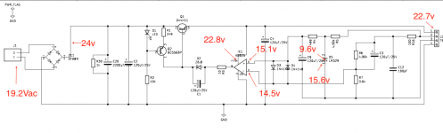
Hi again,
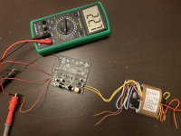
I put together my board... and it doesn't work :-(
Output voltage is 22.7 instead of 12v.
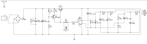
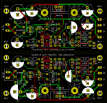
To learn the process for make a pcb, I design my own board on your schematic (attached).
I only added the diodes bridge stage.
My transformer give me an output of around 19v.
These are the value of my resistors (target 12v output):
R6 = 12k
R7 = 8.87k
Could you suggest me a troubleshooting steps to try to fix the problem?
ps: I know, I have to change the capacitors and the heatsink... are provisionals...
Thank you very much.
I put together my board... and it doesn't work :-(
Output voltage is 22.7 instead of 12v.
To learn the process for make a pcb, I design my own board on your schematic (attached).
I only added the diodes bridge stage.
My transformer give me an output of around 19v.
These are the value of my resistors (target 12v output):
R6 = 12k
R7 = 8.87k
Could you suggest me a troubleshooting steps to try to fix the problem?
ps: I know, I have to change the capacitors and the heatsink... are provisionals...
Thank you very much.
Attachments
Last edited:
So the transformer does not provide 19V, but much more. Keep that in mind.
First check is to verify that the sense lines are connected, both output and ground.
Your clips on those wires seem flaky, you never know if the contacts are good. Make that reliable first.
If it then still does not work, verify the voltages on the opamp input pins.
What are they, and if there is a difference, is that difference consistent with the opamp output voltage?
In other words, if +in is larger than -in, is the output positive, and vice versa?
Jan
Ok, I will check.
I tested my transformer output, it is about 19v. Declared on label is 15v.
I tested my transformer output, it is about 19v. Declared on label is 15v.
Last edited:
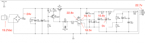
Hi,
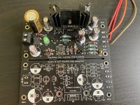
senses lines are connected.
Please look the image attached, I write on top all the voltages that I have tested.
These are the value of my resistors (target 12v output):
R6 = 12k
R7 = 8.87k
Thanks for your help.
senses lines are connected.
Please look the image attached, I write on top all the voltages that I have tested.
These are the value of my resistors (target 12v output):
R6 = 12k
R7 = 8.87k
Thanks for your help.
Attachments
Last edited:
Agree. The bottom of D5 should be zero.
Your output voltage should then be:
Across 7.5k = 6.9V. Therefor, across 12 k is 12k/7.5k*6.9 = 11V. So total will be 17.9V.
Jan
Your output voltage should then be:
Across 7.5k = 6.9V. Therefor, across 12 k is 12k/7.5k*6.9 = 11V. So total will be 17.9V.
Jan
Last edited:
Could the Q2 transistor is inverted respect the footprint?
https://www.mouser.es/datasheet/2/308/BC556BTA-1118603.pdf
I mean the pin numbers. (1-2-3 instead of 3-2-1)
https://www.mouser.es/datasheet/2/308/BC556BTA-1118603.pdf
I mean the pin numbers. (1-2-3 instead of 3-2-1)
If the resistor values are what you built I would expect to see the LM329 voltage at the + input of the op amp (about 6V9 as I remember) and the close to the same voltage on the - input. For that to happen the output needs to be about 2.4 times that determined by the ratio of the 3K6 resistor and the 4K99 plus 100R, which is about 16V7.
Sorry I check it again. Is it 0v.
If can help, the led just flash for a second when I connect the main, and after it switch off.
If can help, the led just flash for a second when I connect the main, and after it switch off.
Attachments
Last edited:
Could the Q2 transistor is inverted respect the footprint?
https://www.mouser.es/datasheet/2/308/BC556BTA-1118603.pdf
I mean the pin numbers. (1-2-3 instead of 3-2-1)
Why do you goof of on that tangent? Several people have pointed out the likely error in your build. Please fix that first.
Jan
- Home
- The diyAudio Store
- Super Regulator