Jan,
Thank you for the update! This clears a lot of confusion. I will look into the schematic again.
Thank you for the update! This clears a lot of confusion. I will look into the schematic again.
There's two resistor on top of each other, one end to Vout, the other end to gnd, the mid to -input opamp. Those are the ones that set the output voltage by 'multiplying up' the ref voltage at the +input of the opamp.
On the schematic in the diyaudio store, R7 (pos) and R14 (neg) are the 'bottom' ones that are connected to gnd, just as the reference. The 'top' is R7 (pos) and R13 (neg), these are connected to Vout.
Agreed?
Edit: 'bottom' I mean at gnd, not physically, sorry. I think in voltages ;-)
There is indeed a cap // R7, R13 to make the voltage division for AC equal to one, for better regulation.
Jan
Hi Jan,
Would you check writing in this link to see if there is any issue on calculating values of R13 and R14? This is hyperlink on diyaudio store product page of superreg.
https://cdn.shopify.com/s/files/1/1006/5046/files/Superreg_customizing.pdf?11150262409842112246
I have read through materials again. Based on your replies to others and me, bottom resistor must have the same voltage with Vref to power opamp (as bottom resistor has one end to gnd, and one end to neg input of opamp). But the document said the opposite. It seems this document had R13 and R14 flipped.
Thanks!
There's two resistor on top of each other, one end to Vout, the other end to gnd, the mid to -input opamp. Those are the ones that set the output voltage by 'multiplying up' the ref voltage at the +input of the opamp.
On the schematic in the diyaudio store, R7 (pos) and R14 (neg) are the 'bottom' ones that are connected to gnd, just as the reference. The 'top' is R7 (pos) and R13 (neg), these are connected to Vout.
Agreed?
Edit: 'bottom' I mean at gnd, not physically, sorry. I think in voltages ;-)
There is indeed a cap // R7, R13 to make the voltage division for AC equal to one, for better regulation.
Jan
Last edited:
Very good catch, you are absolutely right. It's R7 and R14 that have the same voltage as the reference (6.9V with the LM329). The other two resistors (R6, R13) thus have Vout-Vref across them.
I'll get the write-up updated. Sorry for any confusion ...
Jan
I'll get the write-up updated. Sorry for any confusion ...
Jan
Done. Courtesy Jason.
https://cdn.shopify.com/s/files/1/1006/5046/files/Superreg_customizing_r2.pdf
Jan
https://cdn.shopify.com/s/files/1/1006/5046/files/Superreg_customizing_r2.pdf
Jan
Jan,
Thanks! I feel this is why you got asked about this calculation a lot previously.🙂
Thanks! I feel this is why you got asked about this calculation a lot previously.🙂
Done. Courtesy Jason.
https://cdn.shopify.com/s/files/1/1006/5046/files/Superreg_customizing_r2.pdf
Jan
Troubleshooting
I have built the superreg per the BOM for +/- 14V. I have a raw supply of +/- 29V. On the positive side, the LED lights, but my output is a little over 7V. On the negative side, no LED illumination and no output. Testing was without a load on the regulators. I have gone over the pcb and no shorts, wrong values, etc.
Is the input voltage too large?
Do I need a load resistor, and what value, to get regulation for testing?
Any other thoughts on troubleshooting?
Many thanks.
A schematic with resistor values would be helpful.Then we can ask for specific measurements to diagnose & fix.
A quick one: did you connect the remote sensing points to the output points?
Jan
A quick one: did you connect the remote sensing points to the output points?
Jan
Hi Jan,
I did not have the remote sense points connected to the outputs when making measurements.
I am using the diyaudio board v2.3 and stuffed with the BOM parts per your project update June 2015.
I did not have the remote sense points connected to the outputs when making measurements.
I am using the diyaudio board v2.3 and stuffed with the BOM parts per your project update June 2015.
With remote sensing connected to outputs and small load resistor (820R), all is well. Both LEDs illuminate and positive and negative outputs are 14.8V
The sensing tells the regulator what the output is, so it can regulate to what it should be.
If those sense points are not connected the regulator doesn't get any information and thus doesn't know what to do.
If this sounds a bit anthropomorphic, sorry about that.
Jan
If those sense points are not connected the regulator doesn't get any information and thus doesn't know what to do.
If this sounds a bit anthropomorphic, sorry about that.
Jan
The sensing tells the regulator what the output is, so it can regulate to what it should be.
If those sense points are not connected the regulator doesn't get any information and thus doesn't know what to do.
If this sounds a bit anthropomorphic, sorry about that.
Jan
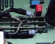
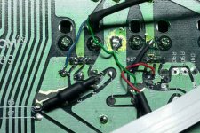
As an example: In my modified Adcom GFP565 Preamplifier I connect the Kelvin sense leads to the output buffer (LT1057) supply pins. This makes that position the lowest impedance nodes on the PCB.
(Come to think of it now, I should replace the Linear Tech buffer on the 565 with the new Texas Instruments BUF634A.)
I also have an SR in an ancient Crown IC-150A preamplifier -- same drill -- the output devices were, I think, LF353 -- now replaced with a compound amplifier.
As an example: In my modified Adcom GFP565 Preamplifier I connect the Kelvin sense leads to the output buffer (LT1057) supply pins. This makes that position the lowest impedance nodes on the PCB.
Pix are from years ago:
Attachments

Good afternoon, I ask for help in setting the superregulator to a current of up to 1.2 amperes, please tell me how can I reconfigure the regulator?
I want to power with SR phono preamp which has 2200mf/25V ordinary ( not low ESR) capacitors near the circuit. SR wires are about 7cm long. Is it too high capacitance? OP-Amps are AD825.
I want to power with SR phono preamp which has 2200mf/25V ordinary ( not low ESR) capacitors near the circuit. SR wires are about 7cm long. Is it too high capacitance? OP-Amps are AD825.
SR shouldn't be bothered by those capacitors -- it's only low ESR caps as bypass across the error amplifier which can create instability issues.
Thank you. I remember 1995 Jung regulator article where MR. Didden suggested maximum 100mf of local circuit capacitance.SR shouldn't be bothered by those capacitors -- it's only low ESR caps as bypass across the error amplifier which can create instability issues.
I don't remember exactly the context. In any case it would never be 100mF, maybe 100uF. Maybe I meant that more than 100uF wasn't useful.
But I agree with Jack, if those caps are at the circuit being powered, it should not matter.
Jan
But I agree with Jack, if those caps are at the circuit being powered, it should not matter.
Jan
I don't remember exactly the context. In any case it would never be 100mF, maybe 100uF. Maybe I meant that more than 100uF wasn't useful.
But I agree with Jack, if those caps are at the circuit being powered, it should not matter.
Jan
Audio Amateur, no. four 1995, page 40: Check the circuit to be powered for excessive decoupling capacity. With these low impedance regulators, more than 100uf or so is overkill, and promotes instability.
Audio Amateur, no. four 1995, page 40: Check the circuit to be powered for excessive decoupling capacity. With these low impedance regulators, more than 100uf or so is overkill, and promotes instability.
Ahh yes, thanks for pulling that up. Today I would still say more than 100uF is overkill. But I would probably not say that more promotes instability, provided those extra caps are a few inch of wire, or more, away.
Jan
- Home
- The diyAudio Store
- Super Regulator