Good afternoon, I ask for help in setting the superregulator to a current of up to 1.2 amperes, please tell me how can I reconfigure the regulator?
More than 1A is stretching it in the current setup. I am working on a higher-current version with thermal and short protection but that will be early next year or later.
What you can do, if you have a few volts overhead available, is use a darlington for the pass device. Things like a TIP120/125 should work. But you must check for oscillations, I don't know how it will work out stability-wise. It might be prudent to leave off the cap across the feedback resistor.
And check the pinout, might be different, don't know.
Jan
The sensing tells the regulator what the output is, so it can regulate to what it should be.
If those sense points are not connected the regulator doesn't get any information and thus doesn't know what to do.
If this sounds a bit anthropomorphic, sorry about that.
Jan
Hi Jan,
I didn't initially connect the sensing wires which I think was the cause of my AD817 'blowing' on the lower 'negative bank' when fed with around 20V DC 🙁
Purchased a new AD817 yesterday, fitted with sensing wires attached and both channels now read ±14.5V output using R6/R7/R13/R14 as 1 K as per BOM for 15V output.
Well done!
Did you try, just for kicks, to put the original '817 back in? I can't imagine a mechanism that would make it to blow in what you described.
Jan
Did you try, just for kicks, to put the original '817 back in? I can't imagine a mechanism that would make it to blow in what you described.
Jan
Well done!
Did you try, just for kicks, to put the original '817 back in? I can't imagine a mechanism that would make it to blow in what you described.
Jan
Hi Jan,
As of the last few days:
In the bottom bank the AD817 gave the same volts as the line (i.e. unregulated).
Top bank was giving 14.5 V.
Swapped the bottom bank AD817 with the top one and the top now ran at 9.6V (or there abouts).
Bottom bank with top AD817 gave 14.5 Volts.
Swopped back again - same issue.
Reversed AD817's again - same results.
Also removed the ICs then chacked the +/- input of each IC (around 7.5V) so I guessed the components were installed properly (also did avisual check before that in the first instance)
(BTW, I'm feeding the DC in via a separate AC/DC LM317/337 adjustable converter)
Received the board months back and when the bottom bank gave problems I put it aside 'until later'. Might have added the one return short for each bank before the second one - when I realised my mistake by not shorting the line/return at the connector.
I think either the in+ or in- pin on the AD817 became faulty - although perhaps it was faulty on receipt.
Not sure.
Anyway, it's now working OK.
BTW, because of R15/R16 @ 100 ohms, the two 'legs' of the voltage divider R6/R7 and R13/R14 are not identical so working with 1K resistances for R6/R13 I think R7 & R14 should be 1k1 for 15V output?
Cheers!
OK, I see. So that '817 is gone. Charge it to the R&D budget ;-)
You are absolutely right on the 1k - 1.1k. But I don't think that it would make any difference in the performance except for a small output DC difference in what you calculate and what you measure. Probably smaller than your DMM accuracy.
I wouldn't put any effort in it.
Jan
You are absolutely right on the 1k - 1.1k. But I don't think that it would make any difference in the performance except for a small output DC difference in what you calculate and what you measure. Probably smaller than your DMM accuracy.
I wouldn't put any effort in it.
Jan
OK, I see. So that '817 is gone. Charge it to the R&D budget ;-)
You are absolutely right on the 1k - 1.1k. But I don't think that it would make any difference in the performance except for a small output DC difference in what you calculate and what you measure. Probably smaller than your DMM accuracy.
I wouldn't put any effort in it.
Jan
Hi Jan,
Quite agree. Just mentioning it in case someone else wonders why they don't get exactly 15.0 V - especially if they're using remote sensing and wonder why 🙂
Thanks for the project and enjoy the festive season.
Tony
A question for Jan. First of all Happy New Year.
Is it possible and/or has been tried increasing the value of C9 in the Linear Audio official schematic, the bypass cap to ground for the non-inverting IC input?
In the simulations I have been running, it does seem to affect the noise curve considerably in the lower frequencies.
Unfortunately I don't have and AD825 LTSpice model, so I have been using the LT1115's. And I wonder how valid my findings might be then.
I'm aware of the "don't change anything" superregulator maxim, so I'm humbly asking if it has been tried and caused serious trouble elsewhere.
Transient analysis with the new cap runs fine, so actual trying on a pcb would be the real proof.
I think it also depends on how accurate the LM329 model is, because that's the noise you are impacting.
As you say, you can try it out, if you can measure noise. Instead of increasing C9 you can also try to increase R4, same effect. Up to 3 or 4k should not make a big difference on the output voltage.
Jan
As you say, you can try it out, if you can measure noise. Instead of increasing C9 you can also try to increase R4, same effect. Up to 3 or 4k should not make a big difference on the output voltage.
Jan
Hi Jan,
Unfortuntely I'm not using an LM329, and would accept any LTSpice model anyone might have to try.
The one I'm using on my sim is an LT1634-5, that comes with LTSpice and should be reliable.
But I did try increasing R4 to 3K and 4K, and the improvements are quite good. How high can I go on it?
I can put the asc files here, if anyone is interested.
Attachments

For a 15 volt regulator try using 4 series connected green LEDs instead of the LM329. It takes a couple of minutes to thermally stabilize when turned on. It maybe a couple of 10ths of a volt higher than 15 volts. (Walt's suggestion in his Gled 431 thread to encapsulate the LED and transistor assembly in silicon to reduce thermal drift when operating works here too). This will get you much closer to 15 volts than the LM 329 while using the original 1k/1k (keeping the parallel value of R6/R7 and R13/R14 close to 499 R is important for other performance benefits).
Changing the resistor values using what is available to set other voltages deviates from this ideal ratio enough to possibly consider using different quantities and colors of series connected LEDs (as Vref) - and replacing the series zener on the op amp output with the same combination of series LEDs (but not blue LEDs- their noisey) will let you keep the 1k/1k and 499R in setting other output voltages.
Yes this suggestion has mild thermal drift, mostly at turn on, but the LED noise is 1 or 2 percent of the LM 329, and yes their are other noise sources such as the opamp and resistors, but it lets you retain the resistor matching ratio which has other benefits. Ideally each voltage would have optimized component values and this one isn’t exactly 15 volts either, but its much closer while retaining the resistor matching - you could change the Led ref current to get 15 volts exactly, but that would throw the resistor matching out which was the idea in the first place. So compromises for each version.
This is a deviation from Walt’s original optimised design and he may well have comments on this suggestion.
Last edited:
On two of the regulators the voltage is +/-30v.
They will power a pair of discrete RIAA preamps.
They will power a pair of discrete RIAA preamps.
Hi Jan,
Unfortuntely I'm not using an LM329, and would accept any LTSpice model anyone might have to try.
The one I'm using on my sim is an LT1634-5, that comes with LTSpice and should be reliable.
But I did try increasing R4 to 3K and 4K, and the improvements are quite good. How high can I go on it?
I can put the asc files here, if anyone is interested.
5k should be OK. The main concern is the noise current through C9. The larger R4, the more that comes into play. This is hard to simulate, and I have no hard data on this. The only sure way to know is to measure it.
Jan
Depending on how close to 30 volts you want to be
Try BZX55C13 with series 1N4149 or BZX 55 C15 for Vref
It still lets you use 1K for R6/R7 but use 1/2 watt Dales and keep them a 1/4 inch off the board, they get warm
Yes maybe 1/2 volt thermal drift at start up, but it stabilizes.
Heres the noise measurements from Christer’s led and zener noise tests in this thread
http://www.diyaudio.com/forums/atta...-leds-zener-diodes-noise_measurements_1_4.txt
BZX55/C12 (0.5W 12V):
#1 @ 1mA: 0.35 0.37 0.37 0.39 0.39 uV
#1 @ 5mA: 0.30 0.28 0.28 0.28 0.30 uV
#1 @ 20mA: 0.24 0.25 0.25 0.26 0.25 uV
#2 @ 1mA: 0.32 0.33 0.32 0.33 0.32 uV (Vr = 11.32 V)
#2 @ 5mA: 0.26 0.26 0.27 0.32 0.26 uV (Vr = 11.37 V)
#2 @ 20mA: 0.25 0.26 0.28 0.24 0.30 uV (vr = 11.42 V)
Last edited:
Depending on how close to 30 volts you want to be
Try BZX55C 13 with series 1N4149 or BZX 55 C15 for Vref
It still lets you use 1K for R6/R7 but use 1/2 watt Dales and keep them a 1/4 inch off the board, they get warm
Yes maybe 1/2 volt thermal drift at start up, but it stabilizes.
The values for R6/R7 for 30v output are 1K1/220, and I want to be as close as possible to 30v. Good to know about the 1/2W Dales for them. Thanks!
So you say I should use BZX55C 13 with series 1N4149 instead of LM329?
Those Christer's measurements are for the regulator's noise? The noise values I get on the simulations, as the curves show, are higher than that. You think the sim results are wrong?
If someone did simulate noise for the regulators on LTSpice and then measured the actual results, please let me know.
OK, I discovered I was doing things badly, because for my 30v the output zener should be half that, so I changed that one to a 15v zener.
Then, as suggested, I swapped my voltage reference also to a 15v zener. Then adjusted R6/R7 to 1K.
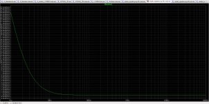
Now the noise curve got much better.
Increasing R4 value brings very little change, so I left it at 499.
The lowest noise I reach is 790uV. Should it be less than that?
Then, as suggested, I swapped my voltage reference also to a 15v zener. Then adjusted R6/R7 to 1K.
Now the noise curve got much better.
Increasing R4 value brings very little change, so I left it at 499.
The lowest noise I reach is 790uV. Should it be less than that?
Attachments
Last edited:
I'm in the process of upgrading or rebuilding my PGA2311 preamp, and I would like your opinion if I should go for the super regulator or the silent switcher.
Plus for the super regulator is that i can keep the mains input and (cheap) transformer. I can then use a ordinary 5 volt regulator for digital side.
The silent switcher has the upside that I can throw out the whole slightly cumbersome transformer and regulator and then integrate my RPi and DAC in the same chassis.
Besides the practical benefits that I listed, are there any good reson to use one or the other?
The great thing about the SilentSwitcher is that you can do away with anything that is connected to the mains. Apart from the clunky transformer, you have absolutely no mains junk coming in.
In your app, with a requirement of +/-15 and a 5V digital, is exactly the app the SS was created for.
The only thing to check is max current draw. 150mA is max for the +/-15, and the 5V digital tops out between 0.5A and 1A, depending on how much you draw from the total and the input voltage.
Do you know the current requirements?
Jan
This is slightly off topic to Superregulator but...
The PGA2311 is a +/- 5V device. The quiescent current is around 10 mA and max output is 50 mA so the current draw is no problem.
I will use a simple China based board and use better quality components, and leave out the standard power reg components.
I might test if buffered input/output will make any difference, but I guess it wont. A OPA1622 will not increase the draw that much.
If I will integrate an external Dac it might be a problem as it needs a regulator of its own.
A lot to think about...
Do you already have the PGA2311? Otherwise you could consider the PGA2320 series which allows +/-15V analog supply for higher dynamic range.
Jan
Jan
Yes, I already have it, but not soldered it in yet. Could possibly just get the chip. And be mindful about the coupling capacitors on the board.
Frequent travels keep me doing a lot of fun stuff 🙁
Frequent travels keep me doing a lot of fun stuff 🙁
- Home
- The diyAudio Store
- Super Regulator