I found my mistake. I used 100nF instead of 100pF for C11 / C12. I removed it and there's no more oscillation. I tried some values to confirm and indeed big values make trouble...
Sorry for that. Thanks for your help.

Yes that will f*ck it up bigtime.
Well done to find it - it is the personal errors that are the hardest to find!
Jan
I recently completed the super regular board (v2.3b) using the standard BOM for +-15VDC output. I've been lurking here a bit reading posts. I'm running a 15VAC CT xformer into my rectification and filter board. I'm getting ~25VDC per rail going into the SR board.
On the output of the SR, I'm getting 25.2VDC on the positive rail and ~17.8VDC on the negative rail. 17.8 volts seems reasonable on the neg rail, but there doesn't seem to be anything being 'regulated' on the positive rail. No voltage on the sense lines on either rail. All measurements were made without a load.
I didn't skimp on the parts, as they were all new, sourced from Mouser here in the states. I've double-checked all the parts placement and values, and everything matches the schematic and PCB layout. I've re-flowed all solder joints as well.
I'm using the AD825 opamp, and have doubled-checked my soldering of the SMD on the 8-pin brown dog adapter. The pins all match. (Actually, this is my second set of AD825).
So, it would seem maybe a bad part, but not sure where to start looking. As with all my projects I buy extra parts, so I can do some replacing as necessary. Any ideas?
On the output of the SR, I'm getting 25.2VDC on the positive rail and ~17.8VDC on the negative rail. 17.8 volts seems reasonable on the neg rail, but there doesn't seem to be anything being 'regulated' on the positive rail. No voltage on the sense lines on either rail. All measurements were made without a load.
Havent looked at the standard BOM, but IMO if the Vref you are using is LM329, then the 17.8Vdc will be strange as well - with all the <1% tolerances in components, the output voltage should be some where near 15V, eg. 15.0x 14.9x... Perhaps the pass transistor on the pos rail is ESD damaged, try substituing it with a to92 transistor and hook up a 10k resistor as load😀
First you need to decide whether you want to diagnose this in a logical way or go for haphazard parts distribution.
If you decide for diagnosing, measure the DC at the opamp inputs, and the output. If you post this here we will be able to see what's wrong and I will explain my reasoning.
Jan
If you decide for diagnosing, measure the DC at the opamp inputs, and the output. If you post this here we will be able to see what's wrong and I will explain my reasoning.
Jan
And ohh yes, you DID connect both the sense and sense returns to the output and output return, of course ... ?
Jan
Jan
I'm in bed reading this on my tablet, so I'll check tomorrow. I want to diagnose this properly. And no, I forgot to connect the sense lines. Duh! Older age is a real bitch. At least that's my excuse. 🙂And ohh yes, you DID connect both the sense and sense returns to the output and output return, of course ... ?
Jan
Rick
The give-away was that you have 25V or so at the output, and zero at the sense. Very likely it will be OK when you connect them.
If not, measure those opamp inputs and outputs.
Jan
If not, measure those opamp inputs and outputs.
Jan
That was it Jan. Once I connected the sense lines the voltages came down to 14.42 on both rails. Now to further raise the voltage to the desired 15v, I adjust the divider R6-R7 and R13-R14? Other thought?The give-away was that you have 25V or so at the output, and zero at the sense. Very likely it will be OK when you connect them.
If not, measure those opamp inputs and outputs.
Jan
Rick
That was it Jan. Once I connected the sense lines the voltages came down to 14.42 on both rails. Now to further raise the voltage to the desired 15v, I adjust the divider R6-R7 and R13-R14? Other thought?
Rick
No I think you're good to go.
Jan
Okay. Thanks for your assistance.No I think you're good to go.
Jan
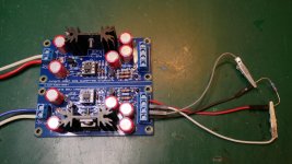
Edit: Here's a pic of my finished board.
Attachments
Last edited:
I can't quite tell from the photograph; did you install "shoulder washers" between the bolt and the metal tab of the TO-220's in post #1650? If not then the tab is electrically connected to the bolt, which is electrically connected to the heatsink, through the hex nut on the back side.
No shoulder washer used. The heatsink is electrically isolated from the PCB so no issue under normal use. Now, if I go probing around.... It is just anchored on the PCB with large solder tabs. The shoulder washers I do have, do not fit those particular heatsinks.I can't quite tell from the photograph; did you install "shoulder washers" between the bolt and the metal tab of the TO-220's in post #1650? If not then the tab is electrically connected to the bolt, which is electrically connected to the heatsink, through the hex nut on the back side.
Edit: Just so you know, this is not a practice I use, especially if the heat sink is NOT isolated from a PCB. But in this situation it works fine.
Last edited:
I bought a bag of 1000 TO-220 shoulder washers, and a bag of 1000 TO-3P shoulder washers, from eBay. They were astonishingly cheap. Now I just reach into my drawer and pull out however many I want. Other hobbyists might enjoy doing the same.
Yeah, the last time I ordered these TO-220 washers was from a BOM from Mouser, and they did not fit! Exact same heatsink and washer part numbers called out in the BOM. I even tried some washers from one of those multi-size washer and pad kits I have, and they didn't fit either. Go figure. I buy a lot of other stuff from eBay, so will look into getting some proper fitting washers.I bought a bag of 1000 TO-220 shoulder washers, and a bag of 1000 TO-3P shoulder washers, from eBay. They were astonishingly cheap. Now I just reach into my drawer and pull out however many I want. Other hobbyists might enjoy doing the same.
I bought 50 MT-200 mica insulators from Electronics Salon on EBay and they were fine - and inexpensive:
Great deals from Electronics-Salon | eBay stores
Great deals from Electronics-Salon | eBay stores
That's the PCB I recently received.Hi. Just checking that the latest Jung-Didden super-reg is v2.3b
Hi all,
I bought 2 Super reg pcb's for use as input stage in my poweramp.
Since I read at linearaudio that it would be possible to reach much higher voltages, changing some components, I bought two pieces of pcb's.
Now it seems it isn't possible since opamp uses same input voltage, which in my case is +/- 65V, and has to be +/-60V regulated.
My question, is it possible to use a LTC6090 or LTC6090-5, which has a max supply voltage of +/-70V,
or do I need to feed AD825 with external voltage supply?
Best regards,
Alex Bartels
The Netherlands
Last edited:
If you need +/-60V out, the opamps each see 60V total so an opamp with for instance +/-36V capability would work. The opamp total supply is the reg output.
Jan
Jan
Thanks Jan for answering this quick!
Is there any preferred opamp which is capable of +/-36V?
I tried to read all the 160+ pages, but it's a lot to read.
What kind of zener do you prefer for 60V regulated output?
Many thanks and cheers! (hmm, it's a bit early for a Bernardus Abt 🙂 )
Alex
Is there any preferred opamp which is capable of +/-36V?
I tried to read all the 160+ pages, but it's a lot to read.
What kind of zener do you prefer for 60V regulated output?
Many thanks and cheers! (hmm, it's a bit early for a Bernardus Abt 🙂 )
Alex
- Home
- The diyAudio Store
- Super Regulator