Part 4 -- Gary is very meticulous -- if you've followed his writing. There's a trade-off with an E-Core or torroid. While, as he mentions, the E-Core is limited bandwidth and doesn't transmit line noise, it's also likely to have higher leakage inductance which may result in some diode ringing.
He also seems to be a "belt and suspenders" guy -- as he uses a bifilar choke on the power supply, which should knock down EMI
He also seems to be a "belt and suspenders" guy -- as he uses a bifilar choke on the power supply, which should knock down EMI
... [the E-core transformer] is also likely to have higher leakage inductance which may result in some diode ringing.
Yes. Fortunately this is easy to eradicate. All you need to do is measure the secondary leakage inductance*, plug it into Hagerman's formula, and install a snubber
- Rsnub = (1 / (2 * Zeta)) * sqrt(Lleak / Ctot)
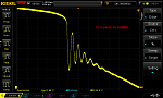
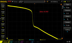
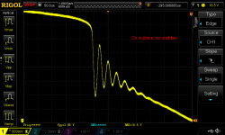
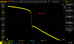
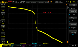
Attached are some measurements made by diyAudio member DNi and posted to a thread in the Power Supplies forum of DIYA. They show an unsnubbed secondary winding, and then three different snubbers with three different damping factors (Zeta). The scope is triggered at the instant when the rectifier diode cuts off.
*This turns out to be rather easy (!).
_
Attachments


Last edited:

In the formula you refer to LLeak is measured from each secondary with primary shorted: correct?
D
D
I've not done any of the background reading, I was hoping that people who had done over the years would present a perfected version.
From this thread it's seems that the 2000 version, as in the Linear Audio article had the additional three pin regulator preceding it, jackinnj posted that that harmed the low out put Z, this latest design therefore would be the 1995 version, but with the sensing chip after the pass transistor from teh 2000 version, but with a developed load sensing circuit added to the schematic by Jan in 2014?
Is that about correct?
No, the load sensing was fully developed in the 95 article
Why don't you do some reading and form your own opinion?
Must faster and reliable than sifting through confusing and conflicting posts 🙂
Jan
In the formula you refer to LLeak is measured from each secondary with primary shorted: correct?
D
I recommend you read Hagerman's snubber paper and also the Quasimodo snubber-design paper.
The most thorough exposition I've ever seen, is in Christophe Basso's textbook, excerpt below. However Basso is concerned with high frequency switching power supplies and the transformers used in HFSMPS. Plain ordinary 50Hz/60Hz mains transformers, probably do not require the same level of precision; they operate on a very leisurely timescale (milliseconds!) so there are no uncomfortable trade-offs between power and noise-reduction.
Basso is careful to isolate and extract ONLY the secondary leakage inductance; however it may be preferable to use the effective secondary leakage inductance in snubber designs, with the primary's leakage inductance reflected (thru the square of the turns ratio) into the secondary. A few SPICE simulations may help you decide which one you prefer.
The first way to skin the cat is (i) measure Lleak and Ctot; (ii) select a desired Zeta; (iii) calculate Rsnub using mathematics.
The second way to skin the cat is (a) connect the actual transformer, rectifier, and snubber together in a working circuit; (b) electrically stimulate the circuit and observe the oscillatory ringing on a scope; (c) adjust Rsnub potentiometer until ringing disappears. This is the "no-math" approach.
_
Attachments

Last edited:
I completed the regulators today, but I have some troubles getting the right voltage.
The target is 5V, so I have the 2.5V reference. I am using the AD825. I get 7.2 V out. The reference is correctly 2.5 and the led is on. If I decrease R6, there is no effect.
Any hint ?
Thanks,
Davide
The target is 5V, so I have the 2.5V reference. I am using the AD825. I get 7.2 V out. The reference is correctly 2.5 and the led is on. If I decrease R6, there is no effect.
Any hint ?
Thanks,
Davide
I can increase the voltage, but not decrease. I suspect that below 7V the AD825 goes off and I need to replace it with the 817.
D.
D.
Read page 38:I completed the regulators today, but I have some troubles getting the right voltage.
The target is 5V, so I have the 2.5V reference. I am using the AD825. I get 7.2 V out. The reference is correctly 2.5 and the led is on. If I decrease R6, there is no effect.
Any hint ?
Thanks,
Davide
http://waltjung.org/PDFs/Regs_for_High_Perf_Audio_4.pdf
I saw that, but I was not sure that it would still apply with new opamps, as in Jan's article, only the voltage reference mod was highlighted.
Anyway, I modified what in the current board are R2 from 10k to 5k and R5 from 4.99k to 2.5k (I actually soldered one more resistor of the same value on top of the existing one) but I still get the same results.
I think the AD817 should be more suitable than AD797 recommended in the article: is it correct ?
Thanks,
Davide
Last edited:
I read that also the value of the Zener D2 might need to be reduced. How much for5 V?
Thanks,
Davide
Sent from my iPhone using Tapatalk
Thanks,
Davide
Sent from my iPhone using Tapatalk
I saw that, but I was not sure that it would still apply with new opamps, as in Jan's article, only the voltage reference mod was highlighted.
Anyway, I modified what in the current board are R2 from 10k to 5k and R5 from 4.99k to 2.5k (I actually soldered one more resistor of the same value on top of the existing one) but I still get the same results.
I think the AD817 should be more suitable than AD797 recommended in the article: is it correct ?
Thanks,
Davide
The ratio of R5/R3 sets the output voltage. R5 should remain 1K. Vout will be Vref*(1+ (R5/R3)). (I don't know why Jan put the parenthesis around R5 in the article.)
We are looking at different schematics. I am referring to the numbers of the boards. The only point that is not still clear to me is if D2/D7 need to be modified and how. In the 1995 schematic this was a 4148, now is a z6.8
Thank you for pointing it out, I did not notice it. With the 4148 in the correct direction I now get 2.5V at the output. I think that I just have to change the op amp. By the way, the board works perfectly for 14v.
Thanks,
Davide
Sent from my iPhone using Tapatalk
Thanks,
Davide
Sent from my iPhone using Tapatalk
Ei core has lower bandwidth than torrid so it lets less AC line noise through, so yes use a C core or EI core transformer especially for preamps, Dac, phono stages
I think the AD817 should be more suitable than AD797 recommended in the article: is it correct ?
Thanks,
Davide
The 797 is not recomended for this application.
For the 5V version, check that the opmp you use is specified for 5V total (+/-2.5V) supply.
Jan
Jan, I got the 817 and things almost work. How to choose the zener at the output of the opamp? With the 6.9v I get 6.9v output, with a 4148 I get 4.2v. I would try a 2.5v next.
D
Sent from my iPhone using Tapatalk
D
Sent from my iPhone using Tapatalk
- Home
- The diyAudio Store
- Super Regulator