... I am curious how a 3.3V regulator (lower voltage that is indicated in the doc) would be implemented ...
All that's necessary is an opamp that can operate from 3.3V supplies, and a VREF diode/IC whose output voltage is within the input common mode range of the opamp. You could even implement the SuperRegulator with the very old and very crappy TLC272 opamp (datasheet) , which has neither Rail-to-Rail inputs nor Rail-to-Rail outputs.
Just be sure not to exceed its output current capabilities [which are tiny], its input common mode range, and its output common mode range. Choose a level shifter which sets the opamp output bias point at about 1.0 volts. Choose a 1.2V shunt voltage reference. Choose an NPN pass transistor with the highest possible beta, and set the PNP current source to ~ 300 uA or below. Voila, it works. Not at the highest possible performance, of course. But it does demonstrate that modern, high performance, rail-to-rail opamps are not mandatory. They are, however, a very good idea.
Question About Testing
Quick question about testing the SuperRegs.
I saw a photo in this thread that shows the load voltage output connected/shorted to the load voltage sense connection and the same for the ground connections. Is this how the SuperReg is tested for proper voltages prior to connecting to the actual circuit requiring power? Was there a 100 ohm resistor across the output of the SuperReg? Sound right?
Read through the articles, but only saw noise test, etc.
Thanks,
Vince
The way I did is the following: I connected output and sense on the board and put a resistor that was giving me a current similar to my load. Walt recommended also to put a 100u cap as load, I guess so it't not pure resistive. Pay attention that if the regulator is not working you get something similar to the raw voltage on the output.
It was also recommended to check the regulator for oscillation with the final load.
D.
It was also recommended to check the regulator for oscillation with the final load.
D.
Use a 500 ohm resistor of minimal 1/4W between V+ and ground and do the same for the negative supply, assuming that you will use a +10V and -10V supply for the B1. Worked for me. I actually used two 1K resistors in parallel. This yields the same result, but the amount of dissipated power will distributed evenly across the resistors.
Last edited:
I am buying some part for the super regs from eBay and some of the exact part numbers aren't available, BC556AP isn't available, available replacements have differing suffixes and some have a different transition frequency 150 -280MHz, BC546BP isn't available, but a whole bunch of replacements with differing suffixes are available. The LM329 are available in a number of varieties, most with a buried zener with greater tolerance and noise, a simpler one without a buried zener has a greater tolerance range but a lot less noise (LM329DZ). Recommendations for choosing these substitute would be greatly appreciated.
I am buying some part for the super regs from eBay and some of the exact part numbers aren't available, BC556AP isn't available, available replacements have differing suffixes and some have a different transition frequency 150 -280MHz, BC546BP isn't available, but a whole bunch of replacements with differing suffixes are available. The LM329 are available in a number of varieties, most with a buried zener with greater tolerance and noise, a simpler one without a buried zener has a greater tolerance range but a lot less noise (LM329DZ). Recommendations for choosing these substitute would be greatly appreciated.
LM329DZ.
The original transistors were of the "2N" variety -- see Walt's blog for the original BOM.
Unless you know a particular parameter is more suited, don't buy a grade BC5xxaI am buying some part for the super regs from eBay and some of the exact part numbers aren't available, BC556AP isn't available, available replacements have differing suffixes and some have a different transition frequency 150 -280MHz, BC546BP isn't available, but a whole bunch of replacements with differing suffixes are available. The LM329 are available in a number of varieties, most with a buried zener with greater tolerance and noise, a simpler one without a buried zener has a greater tolerance range but a lot less noise (LM329DZ). Recommendations for choosing these substitute would be greatly appreciated.
buy b grade or c grade.
Ignore the last script after the b/c
i.e. buy bc546b or 556b for the higher Vce0 and bc550c or 560c when you want higher hFE, but at the lower Vce0.
Unless you know a particular parameter is more suited, don't buy a grade BC5xxa
buy b grade or c grade.
Ignore the last script after the b/c
i.e. buy bc546b or 556b for the higher Vce0 and bc550c or 560c when you want higher hFE, but at the lower Vce0.
Agree. The reason I used the BC series is that in Europe they are usually used in the same roles as the 2N series in US. As noted, Walt's site has the 2N numbers.
Generally speaking, any small signal transistor that has similar specs will do.
Jan
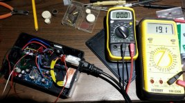
Mostly finished and tested. For some odd reason I'm getting 31 volts dc out of an 18 volt X 2 secondary toroid.
was aiming for 25.5olts, 384 mA.
Using it in parallel to double current and followed the toroid manufacturer's Pdf for wiring. ~32 volts after rectifiers too.
The reg is working fine at 19 volts. I calculated for 18 volts but it's ok for the B1. Caps are 35v.
Shunts and zener are 9.1v. R6/7 are 1k.
Amveco transformer but goes by other names as well.
Any idea why getting these readings? I have reversed the toroid's primary on hot and neutral. Could this cause the hight voltage?
http://www.digikey.com/product-detail/en/62034/1295-1057-ND/3881369
Attachments
Last edited:
Light loading on small toroids always gives you appreciable higher reading. Their 'regulation' is not very good; they are designed to deliver at least the rated voltage at rated current. What's the VA spec of that xformer?
Jan
Jan
Spec sheet says 7VA. That's tiny. Could it cause damage?
The load was 1k and 750 ohm resistors installed one at a time.
The load was 1k and 750 ohm resistors installed one at a time.
BTW- tried the AD8599ARZ opamp and it didn't work. Output was only 11v.
Unfortunately they are expensive, but fortunately when buying 4700uF caps, I picked up a few AD817 opamps. Dropped right in and get 19v.
Unfortunately they are expensive, but fortunately when buying 4700uF caps, I picked up a few AD817 opamps. Dropped right in and get 19v.
Spec sheet says 7VA. That's tiny. Could it cause damage?
The load was 1k and 750 ohm resistors installed one at a time.
No damage but such a small xformer runs pretty high if not loaded down to spec. Nothing to worry about as long as your caps can stand the voltage.
Jan
Mostly finished and tested. For some odd reason I'm getting 31 volts dc out of an 18 volt X 2 secondary toroid.
was aiming for 25.5olts, 384 mA.
Using it in parallel to double current and followed the toroid manufacturer's Pdf for wiring. ~32 volts after rectifiers too.
The reg is working fine at 19 volts. I calculated for 18 volts but it's ok for the B1. Caps are 35v.
Shunts and zener are 9.1v. R6/7 are 1k.
Amveco transformer but goes by other names as well.
Any idea why getting these readings? I have reversed the toroid's primary on hot and neutral. Could this cause the hight voltage?
62034 Talema Group LLC | 1295-1057-ND | DigiKey
That's about right.Spec sheet says 7VA. That's tiny. Could it cause damage?
The load was 1k and 750 ohm resistors installed one at a time.
A 7VA 18Vac 25% regulation transformer fed with rated primary voltage will output 18*1.25 = 22.5Vac. Convert that to DC using sqrt(2) and you get 31.8Vdc
Subtract a little for two diode drops passing near zero current and you have ~30.8Vdc across the smoothing capacitor.
Increase the Mains voltage a bit and you have well over 31V. subtract a lot for the sagged voltage when delivering substantial current.
18Vac 7VA has a Maximum continuous current of 194mAdc
1k with 31Vdc across it is only 31mA
add on 750r for 41mAdc.
Combine them for 72mA. But by them the voltage will be down a bit so <70mA delivered.
Last edited:
- Home
- The diyAudio Store
- Super Regulator