Would a CRC supply be OK for the SuperRegs?
The short answer is yes, but if you read the part 4 of the articles you find all the details. A LC is recommended.
D
Sent from my iPhone using Tapatalk
see post 474! ckt works (well) with ad817, @5V w/2.5V Vref
Jan, I got the 817 and things almost work. How to choose the zener at the output of the opamp? With the 6.9v I get 6.9v output, with a 4148 I get 4.2v. I would try a 2.5v next.
D
So, I tried few vales for the zener and I settled for a 4.1 V. I got 5.2 V output. With a 10k resistor in parallel with R6, I get 5V sharp.
Reducing the resistors like Jan recommended in the article does not seem to affect the output voltage, but I kept the lower values. Zener between 2.5 and 5V gave all the same results.
I hope I did it right.
Thanks,
Davide
Reducing the resistors like Jan recommended in the article does not seem to affect the output voltage, but I kept the lower values. Zener between 2.5 and 5V gave all the same results.
I hope I did it right.
Thanks,
Davide
So, I tried few vales for the zener and I settled for a 4.1 V. I got 5.2 V output. With a 10k resistor in parallel with R6, I get 5V sharp.
Reducing the resistors like Jan recommended in the article does not seem to affect the output voltage, but I kept the lower values. Zener between 2.5 and 5V gave all the same results.
I hope I did it right.
Thanks,
Davide
Looks like we have a disconnect here, literally and figuratively. If you want 5V out, headroom is limited and the op amp is critical. The ad817 does work, as described way back when. Use a 2.5V ref like the lm336-2.5, with adequate current. The 817 is OK with a 2.5V input, so that part is covered.
But!!!!! You must make sure that the diode at the op amp output is POLARIZED CORRECTLY. If it is a 4148 (ok for 5v), the cathode goes towards the OA output in a plus regulator. Note! This diode MUST be able to conduct to control the output! If you are attempting to regulate 5V, any zener is not the best choice here. That is likely the problem, if your output is way too high.
You might also try a RED LED for this diode. That way it will light up and tell you it is happy (and Vout is very likely correct).
Good luck with it..
Is it OK to use 11 ohm at R3 an R10? I have .25w 22 ohm resistors that can be paralleled.
Thought I had a box of 10 ohm but they are 100 ohm.
Thanks
Vince
Thought I had a box of 10 ohm but they are 100 ohm.
Thanks
Vince
Looks like we have a disconnect here, literally and figuratively. If you want 5V out, headroom is limited and the op amp is critical. The ad817 does work, as described way back when. Use a 2.5V ref like the lm336-2.5, with adequate current. The 817 is OK with a 2.5V input, so that part is covered.
But!!!!! You must make sure that the diode at the op amp output is POLARIZED CORRECTLY. If it is a 4148 (ok for 5v), the cathode goes towards the OA output in a plus regulator. Note! This diode MUST be able to conduct to control the output! If you are attempting to regulate 5V, any zener is not the best choice here. That is likely the problem, if your output is way too high.
You might also try a RED LED for this diode. That way it will light up and tell you it is happy (and Vout is very likely correct).
Good luck with it..
Thanks!! I think the 4.1V zener is conducting, i can measure the full zener voltage. I tried the red led( why red and not green?) and it also works, giving a sligtly lower voltage (5.010V vs 5.020) if you think led is a safer option, I'll stick with it. What about the values of R2 and R5? I currently have the values recommended in the old article by Jan for 5 V. I could not see any difference.
Thanks,
Davide
An externally hosted image should be here but it was not working when we last tested it.
An externally hosted image should be here but it was not working when we last tested it.
Everything by the books.
D.
Thanks!! I think the 4.1V zener is conducting, i can measure the full zener voltage. I tried the red led( why red and not green?) and it also works, giving a sligtly lower voltage (5.010V vs 5.020) if you think led is a safer option, I'll stick with it. What about the values of R2 and R5? I currently have the values recommended in the old article by Jan for 5 V. I could not see any difference.
Thanks,
Davide
Sorry but I can't follow reference designations w/o a sch. *If* r5 is the one setting the ref diode current, then it should be adequate to set a current of 2.5V/Iref. See LM336-2.5 ds, "Typical Applications, 2.5V Reference". RED leds will have a slightly lower Vf than green. Use the one that positions the op amp output closest to mid-rail, i.e., ~2.5V. I doubt that the 4.1V zener comes anywhere near mid-rail, so that should NOT be used. If the op amp is sitting lower than around 1.5V above GND, it is not good.
Thanks!! I think the 4.1V zener is conducting, i can measure the full zener voltage. I tried the red led( why red and not green?) and it also works, giving a sligtly lower voltage (5.010V vs 5.020) if you think led is a safer option, I'll stick with it. What about the values of R2 and R5? I currently have the values recommended in the old article by Jan for 5 V. I could not see any difference.
Thanks,
Davide
If anything in series with the opamp changes Vout, your reg is not working properly.
The value of the opamp output series device, be it diode, LED or zener is so that the opamp can have its output away from the pass transistor base to avoid opamp saturation against its supply.
Read that again. Now read Walt's reply to that again.
Sorry - somebody had to say that, no offense intended.
Jan
Need a little help here. Almost done! 🙂
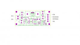
Can some one clarify the in and out of the v2.2 board?
Looking at the board from left to right, J1 top pad looks like it's negative and bottom pad looks positive. But as I read the article, it sounds like the opposite. Please see attached and tell me if this is correct or not.
Thanks,
Vince
Can some one clarify the in and out of the v2.2 board?
Looking at the board from left to right, J1 top pad looks like it's negative and bottom pad looks positive. But as I read the article, it sounds like the opposite. Please see attached and tell me if this is correct or not.
Thanks,
Vince
Attachments
Need a little help here. Almost done! 🙂
Can some one clarify the in and out of the v2.2 board?
Looking at the board from left to right, J1 top pad looks like it's negative and bottom pad looks positive. But as I read the article, it sounds like the opposite. Please see attached and tell me if this is correct or not.
Thanks,
Vince
You're absolutely right Vince, the top of J1 is the negative terminal and the bottom is the pos terminal.
I will fix this.
BTW Where did you gt that drawing I don't think I made it?
Jan
Last edited:
It appears that the link for the user guide you get from the DIY store did not point to the latest version.
I took the latest versions and corrected it as per Vince's findings, see attached.
The BoM is correct for the V2.2 with the remote sense filters. Also removed the connectivity list from the BoM as this is now shown in fig 2.
I will see how I can get the link in the DIY store to be updated to point to his version. That file will also be higher resolution.
Sorry for the confusion,
jan
Attachments
Last edited:
Jan,
the pics in your pdf do not show well. (@75% they are acceptable, but too small)
When expanded (to 125%) the detail becomes almost illegible.
the pics in your pdf do not show well. (@75% they are acceptable, but too small)
When expanded (to 125%) the detail becomes almost illegible.
One other thing. R5 and R16 are a bit close for comfort. Can R5 designition be placed above instead of besides R16 in the parts placement photo?
Jan,
the pics in your pdf do not show well. (@75% they are acceptable, but too small)
When expanded (to 125%) the detail becomes almost illegible.
Yes I know, I had to reduce the resolution to get within the 1MB for PDF on the DIYaudio site.
The version I send to Jason is high res like I said.
Jan
One other thing. R5 and R16 are a bit close for comfort. Can R5 designition be placed above instead of besides R16 in the parts placement photo?
Of course 😉
jan
Attachments
Some level shifter thoughts on 5V
What Jan and I are saying is that attention needs to be paid to where the op amp output settles, especially in a 5V reg where headroom is critical, and the op amp is *not* a rail-rail type. While the recommended AD817 is not R-R, it does have high Iout, by design (it is a video part, spec'd for driving 75 ohms). Being prudent should direct one to keep pin 6 to never be closer than about 1.5V from either rail, which for 5V, means a range of 1.5 to 3.5V. Anywhere between these limits is very likely OK. Why? Because the part is actually spec'd for a range of 1.5 - 3.5V, when driving a 500 ohm load. Here the load is less, so the range cited is actually conservative.
Let's use an example of actual voltages for a 5V reg. For Vout=5V, the NPN pass xstr base will be at ~5.6V. To center the op amp precisely at 2.5V, there should be a (zener/LED/cell) drop of 5.6 - 2.5 = 3.1 (ideally). So, any part (or parts-in-series) that exhibits a fwd drop of ~3V will be good. If one can find a zener that shows such a drop, it will work OK. The problem there is that low voltage zeners tend to be inexact for voltage, both for tolerance and change vs. current.
A single Green LED will drop around 1.8-1.9V, so using that will cause the op amp to rest at 5.6 - 1.8 = 3.8. This would very likely work, but is outside the safest range. Two such LEDS in series would bias the op amp at 5.6 - 3.6 = 2V. And, two series Red LEDs will drop ~1.6 + 1.6V = 3.2V, which sets the op amp at 5.6 -3.2 = 2.4, which should be fine.
Actually, this "two-series-Red-LEDs" could be the optimum selection setup, for a 5V reg. Why? LEDs are much more quiet than any zeners. One could wire the two RED LEDs up as a single unit, and mount this assembly in the PCB's diode location (with correct polarity of course). Now you have a good level shifter, plus a free pilot lamp, at miniscule cost.
Finally, I would reiterate Jan's caution(s), above. But don't change the op amp, unless you *fully* understand all of these ramifications! So, go forth and regulate those (low) volts!
If anything in series with the opamp changes Vout, your reg is not working properly.
The value of the opamp output series device, be it diode, LED or zener is so that the opamp can have its output away from the pass transistor base to avoid opamp saturation against its supply.
Read that again. Now read Walt's reply to that again.
Sorry - somebody had to say that, no offense intended.
Jan
What Jan and I are saying is that attention needs to be paid to where the op amp output settles, especially in a 5V reg where headroom is critical, and the op amp is *not* a rail-rail type. While the recommended AD817 is not R-R, it does have high Iout, by design (it is a video part, spec'd for driving 75 ohms). Being prudent should direct one to keep pin 6 to never be closer than about 1.5V from either rail, which for 5V, means a range of 1.5 to 3.5V. Anywhere between these limits is very likely OK. Why? Because the part is actually spec'd for a range of 1.5 - 3.5V, when driving a 500 ohm load. Here the load is less, so the range cited is actually conservative.
Let's use an example of actual voltages for a 5V reg. For Vout=5V, the NPN pass xstr base will be at ~5.6V. To center the op amp precisely at 2.5V, there should be a (zener/LED/cell) drop of 5.6 - 2.5 = 3.1 (ideally). So, any part (or parts-in-series) that exhibits a fwd drop of ~3V will be good. If one can find a zener that shows such a drop, it will work OK. The problem there is that low voltage zeners tend to be inexact for voltage, both for tolerance and change vs. current.
A single Green LED will drop around 1.8-1.9V, so using that will cause the op amp to rest at 5.6 - 1.8 = 3.8. This would very likely work, but is outside the safest range. Two such LEDS in series would bias the op amp at 5.6 - 3.6 = 2V. And, two series Red LEDs will drop ~1.6 + 1.6V = 3.2V, which sets the op amp at 5.6 -3.2 = 2.4, which should be fine.
Actually, this "two-series-Red-LEDs" could be the optimum selection setup, for a 5V reg. Why? LEDs are much more quiet than any zeners. One could wire the two RED LEDs up as a single unit, and mount this assembly in the PCB's diode location (with correct polarity of course). Now you have a good level shifter, plus a free pilot lamp, at miniscule cost.
Finally, I would reiterate Jan's caution(s), above. But don't change the op amp, unless you *fully* understand all of these ramifications! So, go forth and regulate those (low) volts!
Last edited:
Dear Walt,
Your explanation is really clear and what I saw empirically confirms everything.
The base of the NPN is a 5.6 V and I had a 4.1V zener, that took the OA output barely above 1.5V. Than I tried 3.0V zener (OA at 3.2V), 3.5V zener (OA at 2.1V), one red led (OA at 3.9C) and two red led (that was my final choice) put the OA at 2.3V.
I think we should frame this discussion in the documentation as the note on the lower voltage application is a bit semplicistic. For academic reasons, I am curious how a 3.3V regulator (lower voltage that is indicated in the doc) would be implemented. I guess that in this application you must choose a rail to rail OA.
Thanks,
Davide
- Home
- The diyAudio Store
- Super Regulator