I've used an even slower opamp and indeed it did not fail. LM741 has a GBWproduct of 1.5 MHz (typ). I've built the super regulator topology using an OP07 opamp whose GBWproduct is 0.6 MHz. (datasheet). Worked just fine! BTW I paired it with a series pass transistor whose fT was more than 300 MHz. Why? So I could unplug the OP07 and try other opamps.Using the super regulator topology with a 741, you can't fail
Consider you have a stable function with the op-amp itself and have a gain of max 6 dB, that is a achievement but if you insert phase shifting elements such as the the pass transistor D44H11(?) with only 40-50 MHz fT, then you will most likely create stability problems.
I'm using a pair of bc550c in parallel right now.
I also just remembered i had a few lmp7731 at hand that i have not tried yet... (GBW 22MHz, Slew Rate 2.4V/uS)
Hello guys,
If I want to use the super reg for BA-3 dual mono what changes do I have to make for 23V rails?
The amp will draw aprox 50mA per rail so what pre regulation is recommanded?
Thanks!
If I want to use the super reg for BA-3 dual mono what changes do I have to make for 23V rails?
The amp will draw aprox 50mA per rail so what pre regulation is recommanded?
Thanks!
About the pass transistor Ft. How important is that because it is used as an emitter follower/ common collector mode, while the Ft is a spec for common emitter mode.
Jan
Jan
Hello guys,
If I want to use the super reg for BA-3 dual mono what changes do I have to make for 23V rails?
The amp will draw aprox 50mA per rail so what pre regulation is recommanded?
Thanks!
Look at post 174 in this thread, Jan explains it very clearly 🙂
I'm using the superregs also with BA-3 as a preamp, and I have the superregs working at 32V.
Because Nelson mentioned the lower distortion compared with the 24V in the BA-3 article.
The 2SJ74BL is max. 25 Volt 😱😱 FAB
Yes. And I would hope that anyone using these regs will at least take the trouble to understand the very simple way to set Vout. What's the fun in building something without having a clue how it works? That's daft in my book!
I get tired of explaining it for 16V and the next guy asks - what would it be for 17V?? Gimme a break!
Jan
I get tired of explaining it for 16V and the next guy asks - what would it be for 17V?? Gimme a break!
Jan
looks like a questment, if i may
Yes wondering how relevant Ft is for this application.
I mean, with the 100% feedback of an emitter follower the bandwidth should be huge, much wider than Ft anyway.
Jan
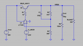
I slapped together a barebones Super Regulator using a 50 MHz opamp (LT1361) and a D44H11 pass transistor: see Figure 1 below.About the pass transistor Ft. How important is that because it is used as an emitter follower...
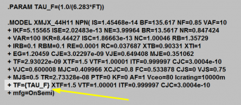
EXCEPT that I made the pass transistor's fT into a user adjustable parameter. SPICE BJT models include a parameter TAUF which is simply (1/2*pi*fT). So I simulated this Super Regulator with pass transistors having many different fT values, see Figure 2 below.
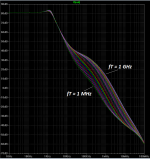
The results are shown in Figure 3. This is the open loop transfer function; notice that changing the fT of the pass transistor, changes the overall loop bandwidth. Does pass transistor fT have any effect at all? Yes. Yes it does.
By the way the frequency response plot clearly shows the output capacitor's "ESR Zero" (reference) around 20 kHz or so. TI didn't lie to you; that's a very real phenomenon.
_
Attachments
Yes. And I would hope that anyone using these regs will at least take the trouble to understand the very simple way to set Vout. What's the fun in building something without having a clue how it works? That's daft in my book!
I get tired of explaining it for 16V and the next guy asks - what would it be for 17V?? Gimme a break!
Jan
Give then the math then there is no excuse.
Hi, Gentlemen,
Here is my report. As said earlier I have designed and built a new PCB incorporating opamp compensation as per Jung's article as well as the proper implementation of the remote sensing RC.
I built it this morning. It is working very fine without any trace of resonance, and that is with my existing load with a PCB on power and ground planes. I have designed and bought a new PCB for the load without using power and ground planes, and I am going to test that one too and see if there is any sonic difference.
I am listening to music right now. It sounds pretty fine!
Thanks to all those helped and for the good chats.
Regards,
Bill
Give then the math then there is no excuse.
Are you kidding? I've done that dozens of time. It's in the article download at the shop. It's just basic lazyness and a lack of interest. But not on my time.
Jan
I slapped together a barebones Super Regulator using a 50 MHz opamp (LT1361) and a D44H11 pass transistor: see Figure 1 below.
EXCEPT that I made the pass transistor's fT into a user adjustable parameter. SPICE BJT models include a parameter TAUF which is simply (1/2*pi*fT). So I simulated this Super Regulator with pass transistors having many different fT values, see Figure 2 below.
The results are shown in Figure 3. This is the open loop transfer function; notice that changing the fT of the pass transistor, changes the overall loop bandwidth. Does pass transistor fT have any effect at all? Yes. Yes it does.
By the way the frequency response plot clearly shows the output capacitor's "ESR Zero" (reference) around 20 kHz or so. TI didn't lie to you; that's a very real phenomenon.
_
Very nice Mark - that is quite useful! Thanks.
Jan
I have not read something more ignorant in a long time. All it takes is the ability to read... which should be expected. Download the manual.Give then the math then there is no excuse.
This discussion is about the ESR of the output cap.
I have been playing with a LTSpice Jung Supereg model - the schematic is the same but the active devices are different - AD825=>LT1028A, D44H11=>BC337, BC556B=>BC327, and so on. I think the creator of the model did not have the models of the active devices hence arbitrarily put on the ones he had on hand.
I don't expect the model to be accurate but I think it should be indicative.
I can now see if I put a 0.1uF film cap at the output it causes resonance / oscillation. So high Q film cap at the output is definitely a no.
However, I found that there is no problem using a low ESR 120uF cap (0.01R - 0.05R) at the output. I can also add a few more of the same low ESR caps at the load without problems. In fact, if the ESR increases to be beyond 0.1R, the phase response gets worse. When it gets to 0.5R or above, the phase goes beyond 180 degrees at the point the regulator oscillates. With this model, lower ESR caps give much better phase response. Note that the Jung regulator was tested by builders using Panasonic FC and possibly Rubycon ZA, which had ESR from about 0.08R to 0.3R, and it worked fine.
I am wondering if some of you who have an accurate LTSpice model found the same thing? or is it only because I don't have the right LTSpice model?
If you also have tried low ESR caps in the regulator, let us know.
I went through some of the old threads discussing the Jung Supereg. I found that (1) Everyone agreed that high Q film caps can not be placed at the regulator output; (2) Some suggested using a high ESR cap at the output but they were guessing because they did not measure or simulate it; (3) Mr. Jung mentioned that the ESR of the 120uF at the output was not considered when the regulator was designed.
We know some of the LDO regulators require specific output caps. I am keen to find out what ESR is the best suitable for the Jung reg.
Last edited:

First run a bode plot to find the troublesome frequency. For one of the original Jung regulators with the AD797 I found this to be around 770kHz.I am keen to find out what ESR is the best suitable for the Jung reg.
Do a "parameter sweep" using an ideal 120u cap and a "parameterized" resistor "Rp" on the output node at this frequency. Put Zout on the y-axis and Rp on the x-axis.
Are you kidding?
Jan
Yes.
Sorry the sarcasm didn't come through.
Yes.
Sorry the sarcasm didn't come through.
My bad - I often am too serious...
Jan
First run a bode plot to find the troublesome frequency. For one of the original Jung regulators with the AD797 I found this to be around 770kHz.
Do a "parameter sweep" using an ideal 120u cap and a "parameterized" resistor "Rp" on the output node at this frequency. Put Zout on the y-axis and Rp on the x-axis.
Jack,
I have been doing those. But the issue is that I don't have the accurate models of active devices. Your 770kHz is indeed the trouble some area from my model too, so possibly my model is not far off.
I like your earlier reply implying that my earlier assumption of no performance degradation of opamp compensation and remote sensing RC was ridiculous. You were not wrong.
Here are some findings in my possibly faulty model:
1. The best ESR value for the output cap seems to be around 0.5R. Higher or lower makes the response worse. My real life test seemed to agree with this. When I changed a cap with ESR=0.3R to a higher ESR cap (yet to be measured) and the sound became better. When I added a low impedance cap at the output, although the scope did not reveal any oscillation, subjective listening showed that it significantly degraded the sound. The value of the output cap does not seem to be matter too much.
2. I have two 22uF at the load. Simulations showed me that the ideal ESR for them was 0.3R. I tried caps there and found the Panasonic FR 50V 22uF sounded obviously better. The cap has an impedance of 0.34R at 100kHz. I tried without them and caps with higher ESR and they sounded worse. So it seems that my simulations were spot on.
3. Opamp compensation: it works and makes it sound better. But when100pF, the original recommended value, was used the sound was worse - muddy. It is currently at 10pF and the sound is fine. It is perceivably cleaner than without. Simulations show that a 10pF degrades the output impedance by 8dB while a 100pF degrades the output impedance by 24dB across the full spectrum from 10Hz to 500kHz.
4. Remote sensing: The recommended RC value was 10nF / 10R. In combination with the 100pF opamp compensation the sound was a bit muddy. Reduced the compensation cap from 100pF to 10pF and the remote sensing cap from 10nF to 1nF made a dramatic improvement on the sound. Simulations showed that I can reduce the capacitor to 220pF and the resistor to 2.2R on the remote sensing RC to get optimum result but I am yet to try this.
Anyone who has an accurate model please share with me.
The above values are possibly not the final, optimized ones. Please do not blindly copy. Let us discuss further, simulate further and experiment further in real life and share our results.
Any inputs from you are appreciated.
Bill
- Home
- The diyAudio Store
- Super Regulator