Oh, one last question I can think of now...
Why does it need a 10R at the output of the error amp? Will 1R do the job? Spice modelling clearly shows that 1R will improve the output impedance a bit comparing to a 10R, if some small R is needed at all.
Why does it need a 10R at the output of the error amp? Will 1R do the job? Spice modelling clearly shows that 1R will improve the output impedance a bit comparing to a 10R, if some small R is needed at all.
If I run 200mA current, will a 30 deg C/W heatsink be sufficient?
But before that question can be answered, we need to establish the voltage drop across the Jung Supereg. Is it 1.5VDC or 2VDC? - assumed that the input is DC, not AC.
For 2VDC voltage drop, dissipation will be 2V x 0.2A = 0.4W. For a 30 deg C/W heatsink, the temperature will rise 0.4 * 30 = 12 deg C above ambient temperature.
That should be very safe, or not?
12 degree temperature rise is not a problem, Q1 will tolerate much greater temperature rises than that with only 200mA.
With the Jung Supereg, can we replace the resistors with more common E24 values, e.g. from 249R to 270R, from 4k99 to 5k6R, from 499R to 1k, from 1k to 2k?
When the FET input AD825 is used the slight increase in input impedance makes no impact on the overall noise performance.
249R is used for R1 which sets the emitter current of Q2, some or all of this current provides the base drive for Q1. Increasing R1 will reduce Q2 emitter current and therefore reduce the maximum regulator output current. However, for a 200mA output you should be OK. Changing R1 to 220R will increase the max. regulator output current but will make the opamp work harder (get warmer).
R4 and R5 are 499 and 4k99 - hese could be changed to 560 and 5k6 respectively. I am not sure why you want to change the 1k (R6 R7) resistors as they are available in E24 and E12. If it is to set a different output voltage the values should be calculated as per Jan's notes (diyaudio store, speregulator board) for the regulator.
Oh, one last question I can think of now...
Why does it need a 10R at the output of the error amp? Will 1R do the job? Spice modelling clearly shows that 1R will improve the output impedance a bit comparing to a 10R, if some small R is needed at all.
I think the 10 ohm resistor is to limit the maximum current to the opamp when charging / discharging the 120uF capacitor across the zener diode, D2. I would not use 1ohm. You could use a higher value than 10R, say up to 22R. The performance of the regulator will be reduced if you make this resistor too large.
With the Jung Supereg, can we replace the resistors with more common E24 values, e.g. from 249R to 270R, from 4k99 to 5k6R, from 499R to 1k, from 1k to 2k?
When the FET input AD825 is used the slight increase in input impedance makes no impact on the overall noise performance.
That should make no difference at all.
Jan
Thanks, guys.
The reason to use 270R instead of 249R is to find the nearest E12 value and to decrease the opamp load. In Jung's article, he said that the original value was 100R. He later increased it to 249R. As a result, the opamp load current was reduced from 10mA to 5mA. I thought 5mA current is still high so increasing the resistor a bit will further reduce the load a bit. I prefer opamps run at lower temperature if possible. As long as the regulator can output 200mA I am OK.
I think the 4k99 resistor value is not critical at all. The 499R resistor value is not important. It sets the DC input impedance to the opamp. So if I choose 1k, it is just easy to remember. The other two resistor values (the original 2 x 1k) should follow the formula given to set the output voltage, and the parallel resistance should be 1k. This matches the DC input impedance of both the positive and negative inputs of the error amp. For the original implementation using AD797, it might be beneficial to have a low input impedance to reduce noise. But for a FET input opamp Ad825, higher impedance does not matter. Once again, increasing the resistor values reduces current and things run cooler.
As for the 10R at the output of the opamp, it definitely increases the regulator output impedance a bit. I think Jung said that it was for stability. I have not thought of the initial charging current of the 120uF cap that follows it. The AD825 does not seem to have current limit. So if there is too much current it can get burnt. But I have no idea how much current the 120uF will draw when charging up and how long that takes. If the 10R is for stability, does it serve the function like a "gate stopper" for the pass transistor? The question is how much lower it can get without causing stability problem?
Since I obtained a Jung regulator LTSpice model, I have spent quite a bit of time playing with simulations, especially with parasitic. I have now basically concluded that remote sensing is a must if the regulator board is away from the load board. Without using remote sensing, the regulator may be reduced to an ordinary regulator. But remote sensing is still not good comparing to having the regulator just right next to the load. This is because the inductance of the wires will degrade the regulator performance at higher frequencies, even if remote sensing is being used. The remote sensing RC could also introduce some peak at output impedance. So now I am redesigning my Jung regulator PCB so that it is suitable to be placed directly on the load and I am going to redesign my load board to include the Jung regulator on it. I think in this way, I will get the ultimate Jung SUPER regulator.
You must regard the simulation as a tool not to replace design work in the lab. The real life is more complicated than the SPICE model you know.
You must regard the simulation as a tool not to replace design work in the lab. The real life is more complicated than the SPICE model you know.
Thanks, Peranders.
Fortunately, Mr Jung and others have completed the design and tests and here we are only using their design. There is no change to the design. It is all about implementing it. Reducing the current slightly, etc, is about tweaking, not redesigning.
People have given their different opinions on how to implement it. Some of them did not originate from Mr. Jung. I think some of the advices from posters may be wrong.
Examples are:
1) Remote sensing cancels the inductance of the wires - this tells only half of the picture because remote sensing does help at audio frequencies but it still degrades output impedance at frequencies around 1MHz comparing to having the regulator right at the load.
2) Remove all or most your capacitors at the load - this seems to be very wrong with my simulations. Removing any high Q film / ceramic capacitors is the absolute right thing to do, but not necessarily electrolytic capacitors. In my simulations, electrolytic capacitors at the load help lower impedance and improve on the phase margin a lot and they are absolutely necessary. My subjective listening test also agreed with this. Simulations show that you can place multiple electrolytic caps there and the capacitance can be above 1000uF in total without problem.
3) Avoid using low ESR caps - This tells only half of the picture. My latest simulations (now uses AD825 and D44H11) showed me that the cap right at the output of the Jung regulator needs to be high ESR. 0.5R should work, 1 or 2R may be better. However, electrolytic capacitors at the load should have relatively lower ESR. Low ESR caps help improves phase margin and lower the output impedance in the MHz region.
Of course, I / my simulations can be wrong.
1) Remote sensing cancels the inductance of the wires - this tells only half of the picture because remote sensing does help at audio frequencies but it still degrades output impedance at frequencies around 1MHz comparing to having the regulator right at the load.
Agreed.
2) Remove all or most your capacitors at the load - this seems to be very wrong with my simulations. Removing any high Q film / ceramic capacitors is the absolute right thing to do, but not necessarily electrolytic capacitors. In my simulations, electrolytic capacitors at the load help lower impedance and improve on the phase margin a lot and they are absolutely necessary.
Fully agree.
3) Avoid using low ESR caps - This tells only half of the picture. My latest simulations (now uses AD825 and D44H11) showed me that the cap right at the output of the Jung regulator needs to be high ESR. 0.5R should work, 1 or 2R may be better. However, electrolytic capacitors at the load should have relatively lower ESR. Low ESR caps help improves phase margin and lower the output impedance in the MHz region.
Somewhat agree. Caps at the load or at any rate away from the reg itself can be low ESR without disturbing the reg stability. However, they can resonate with the wiring inductance, and cause ripples at the load, without bothering the reg.
In general you can say that decoupling caps, that are used to lower or suppress ripple, should be lossy. You can only remove unwanted stuff if there is a loss element, otherwise you just move the ripple etc to another place.
Jan
Last edited:
Caps at the load, like 0605 or 0803 ceramics stop the inward migration of radio frequency interference. Analog Devices has a comprehensive application note on the why's ...
Caps at the load, like 0605 or 0803 ceramics stop the inward migration of radio frequency interference. Analog Devices has a comprehensive application note on the why's ...
You raised a good question.
But in order to use them we need some "separation" between them and the regulator, and we need to reduce the bandwidth of the regulator (by remote sensing RC and/or opamp compensation) to avoid oscillation. When the bandwidth of the regulator is set to high (AD825 has a bandwidth of 41MHz) it can interact with the ceramic caps. When the bandwidth of the regulator is set to low it looses its ability to regulate at higher frequencies.
Where to set the line? That is difficult. I won't be happy with a simple answer: "you need to have some wires in between". I do think that combining the regulator with ceramic caps will probably end up better, because the ceramic can work higher up in frequencies than the regulator.
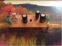
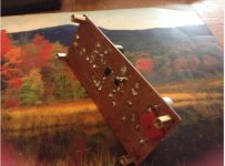
my build!
Notes:
-sole jfet ccs (2n5457)
-last reference voltage cap is a ceramic 4.7uf (cap is determinant to sound and ceramic sounds better in balance than any other (electrolytic,film,sp-cap) to me, for 3.3v clock supply). the sound is now similar in this regard compared to the venerable Salas PSU.as per official schematic, the lytic cap made the sound high pitched and not enjoyable in the long run.
pass bjt is bc550b (this high gain type sounds definitely better than other lower gain gain caps) and plan to parallel to lower output Z further.
-i'm waiting for a part for my "special" Salas build for final battle.
-lmp7731 is the op-amp fed from output
-i made a quick point to point build previously and i THINK the one i'm presenting sounds better. Short cable to load defenitely is a major improvement.
-i have no scope, so only subjective impressions.
Attachments
Last edited:
Caps at the load, like 0605 or 0803 ceramics stop the inward migration of radio frequency interference. Analog Devices has a comprehensive application note on the why's ...
I think I now understand why the first Jung Supereg I built oscillated.
The load consists of power and ground planes that form a 1.1nF capacitance between -V and 0, and 200pF between +V and 0. These are low ESL, low ESR, high Q capacitors.
The way I got it to work was to install a remote sensing RC, even though the distance is hardly remote. When C=10nF and R=10R the sound was a bit dull. When C=1nF and R=1R it oscillated mildly. When C=1nF and R=10R it didn't oscillate but the sound was bright. Now I am using C=10nF and R=4R.
I am still tossed between the ideas of having no high Q caps at the load and running the Jung Supereg in full bandwidth, and having power and ground planes at the load (to reduce inductance and work as RF capacitors) and limiting the bandwidth of the Jung Supereg.
Which one works and sounds better? I have no idea.
P.S. I don't understand why the small high Q capacitance would cause problems. According to my simulation, the 1.1nF coming from the planes would cause a phase reversal at 71MHz. The Jung Supereg should have a close loop below that. The AD825 has a bandwidth of 41MHz. Why the phase reversal at 71MHz causes oscillation at the Jung Supereg?
Readers who, like me, have built or have considered building a Super Regulator using a MOSFET pass transistor instead of a bipolar, are invited to read
http://www.diyaudio.com/forums/soli...m-not-higher-than-bipolar-gm.html#post4703902
http://www.diyaudio.com/forums/soli...m-not-higher-than-bipolar-gm.html#post4703902
PNP & NPN for superreg 2.2
I'm looking at parts for a super reg and can't get a go to for the Q2 & Q4 bipolar transistors. Mouser no longer recognizes the PN. I do not know the important data numbers to make a good choice. I know its DIY, however a little help would be welcome. A recommendation for the DIY Store, if you want to sell more boards. Mouser has a tool which allows your customers to order a BOM, one click, pay the man and done. Might be worth looking into. You could at least Maintain your BOMs in a current status on the diyaudio site. Just a short rant. Thanks.
I'm looking at parts for a super reg and can't get a go to for the Q2 & Q4 bipolar transistors. Mouser no longer recognizes the PN. I do not know the important data numbers to make a good choice. I know its DIY, however a little help would be welcome. A recommendation for the DIY Store, if you want to sell more boards. Mouser has a tool which allows your customers to order a BOM, one click, pay the man and done. Might be worth looking into. You could at least Maintain your BOMs in a current status on the diyaudio site. Just a short rant. Thanks.
Hello,
I purchased the V2.3 boards and have found all the parts. However I have no idea which Led would be OK for D1-D6, could someone post a link to a suitable part in Mouser ??
I have also read that some Leds are noisier than others, I'm afraid to make a mistake if I select this myself.
Thank you,
C.A.
I purchased the V2.3 boards and have found all the parts. However I have no idea which Led would be OK for D1-D6, could someone post a link to a suitable part in Mouser ??
I have also read that some Leds are noisier than others, I'm afraid to make a mistake if I select this myself.
Thank you,
C.A.
- Home
- The diyAudio Store
- Super Regulator