The BJTs are facing the wrong way, aren't they?
The silk screen is misleading, if they are in the wrong way.
Also the Galo 1995 article recommended raw dc power supply looks wrong as well. The negative section look exactly like the positive section. The cap isn't reversed in the negative section, and probably wrong at the bridge as well. I'm not sure about this so don't chew me out. I guess it depend on what reference is...
looks OK to me, the BJT's. See picture of mine
Attachments
Pic in the article shows the tab pointing out.
I check all the resistors and they are ok. Not sure where the problem is.
I'm using 2.3v board.
I check all the resistors and they are ok. Not sure where the problem is.
I'm using 2.3v board.
Attachments

Last edited:
you said something about not connecting the sense. I think you must connect them to work correct...
Pic in the article shows the tab pointing out.
I check all the resistors and they are ok. Not sure where the problem is.
Vince you could always check device polarity by checking which pin is, say, the emitter from the data sheet and see if it is connected to the right tracks on the PCB.
The other thing is checking the reference voltage, is that 6.9V? (For the 329).
Another thing you can check is whether the voltages on the two opamp pins are equal, if they are not the opamp isn't regulating, then look at the opamp output, is it in accordance with the difference in inputs? For instance, if the -input is higher than the +input the output should be near gnd, and vice versa. My hunch is the +input will be larger and the opamp output maxed out.
A quick check would be to replace the 6.8V output zener with a say 3 or 4 V one.
You really should do some testing it will help to diagnose it and you'll learn in the process.
Jan
You are right picture in the article looks..... wrong
I build at least 3 superregulators as shown on my picture, and they all work.
Do you use the Original D44H11 and D45H11 transistors?
I build at least 3 superregulators as shown on my picture, and they all work.
Do you use the Original D44H11 and D45H11 transistors?
Used:
LM329DZ
6.8v zener 500mW
AD817AZN
BC556ABU
BC546ABU
D44H11TU
D45H11
I built a B1 with 18v and it was fine but I think it was the 2.2v of the super reg board.
With the tab facing out, the D44h11is backwards.
Checked against part specs and traces on the board.
So the silkscreen is correct, the photo is wrong, which is board v2.0.
I'll reverse the large BJTs again then take measurements.
Thx
Vin
D2 has 6.8v across it. K is 8.4v and A is 1.6v.
Voltage at opamp by pin- 1= .56v, 2 & 3= -.05v, 4= 0v, 5= .56v, 6= 7.83v, 7= 1.56v, 8= 0v
Bc556 pin 1 is 8.4v, 2 is 13.26v, 3 is 13.92v
D44h11 pin 1 is 8.40v, 2 is 15v, 3 is 7.83v
LM32- .07v on both pin 2 & 3, no voltage across 2 & 3.
No voltage at D3, D4, R4.
I swapped the opamps, but no change.
Wiggling C9 makes the voltage go up.
Any ideas?
The good news is I wasn't cranking up the lab DC high enough. At around 20v the reg output leveled out at 17.66v. 25v output stayed at17.66v. I also shorted the sense to corresponding outputs. Don't know if that is good when just using a dmm to measure.
I calculated for 12v. Also used recommended resistors to set at 12v. 1k/750 ohm for dividing resistors.
Does it sound like something is faulty or just a variation in parts like the bjts?
Can I try a 1k resistor to see what I get or is it too late?
If I can get it close to 12v out, all is good.
Edit: 1k brought it down to 14.83v. 250 ohm brought the voltage down 2v.
Thanks
Vince
Last edited:
Sense Connections
Finished the SuperReg and a CRC supply as its frontend. 5400uF max capacitance.
I'm sure it has been stressed before, but I'll repeat it here for anyone new to this power supply. Test the SuperReg with the sense connections in place. If not connected, you will get crazy readings! Used wire jumpers, which seems to do the trick.
Question 1- is 3.15v enough headroom between the raw supply output and the output of the SuperReg. 5v or more is mentioned. I was hoping this was only in the case of a problem. There is room to lower the Regs output, but would like to know your thoughts.
Question 2- Can all the grounds and their sense wires be connected to the same ground of a +V, ground, -V circuit power connection. In other words, 4 wires to 1 connection point. Can this be done safely and effectively?
Thanks,
Vince
Last edited:
It might have been asked before (could not find it..) but is it possible to modify the regulator to get 2A continuously at 5V ?
I am aware that it would require a larger heatsink.
Best regards,
Ronald
I am aware that it would require a larger heatsink.
Best regards,
Ronald
Probably.It might have been asked before (could not find it..) but is it possible to modify the regulator to get 2A continuously at 5V ?
I am aware that it would require a larger heatsink.
Best regards,
Ronald
If like the previous poster you have say 3.5V of Vdrop across the regulator and you draw 2A through the regulator then the dissipation across the main voltage dropping element will be ~7W. That will require an appropriate heatsink and components selected to suit that high continuous current.
7W for a To126 device with a max rating of 5W to 20W is probably not on.
A To220 device with a max rating of 20W to 80W would probably do, if it's other parameters are suitable.
tingtong5, what is your application? I suspect that a 10 W 5V design can't need ultralow noise supply voltage. Is it digital or analogue?
Besides the power dissipation you also have to consider the base current to the pass transistor. The poor opamp must be able to handle 30-40 mA and this is too much with the present design. You'll need an emitter follower (like I have) after the opamp be with even this fixed you could end up with stability problems => You'll need time and skills for development and verification.
Besides the power dissipation you also have to consider the base current to the pass transistor. The poor opamp must be able to handle 30-40 mA and this is too much with the present design. You'll need an emitter follower (like I have) after the opamp be with even this fixed you could end up with stability problems => You'll need time and skills for development and verification.
An improved PSU for a squeezebox touch...
I do understand now that this is not trivial and the superreg is not first choice for this application.
I do understand now that this is not trivial and the superreg is not first choice for this application.
Have some of the boards on order.
Nowhere have I seen any recommendations for the raw supply.
BELLESON recommends nothing more than a rectifier and a capacitor after the transformer for their implementation of the super reg. Is that the case for this one, also? Was thinking with the elimination of the 317 it might be good to add more filtering to the raw supply? Curious what others think.
Another thing I wonder about (of course, I will try it) but has anyone used a pulldown resistor on the output of the reg? I am going to use 750R - my circuit does not draw much current I could probably bleed off more than that. Another thing that I found was beneficial with the BELLESONs and was recommended by Brian as something to try. Seems like a god idea to me.
Take care,
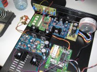
This weekend I built a Jung/Didden super reg with CRC filter and with a 2+ amp toroid for the B1. No other filtering. Im blown away with the results.
A friend passed on a simple tweak. Simply raise the transformer away from the chassis. I also removed the metal mounting hardware and used nylon bolt, washer and nut. I used plexiglass, but wood could work as a riser. Really good results.
I wish I could thank the original person who suggest this for DACs. I'll ask my friend.
Btw I've used the Belleson regs and like them very much.
Last edited:
Thanks for the advice.
Not a fan of toroids for preamps so I am using HAMMOND split bobbins but I find these, too, benefit from isolation from metal. One reason I do not use metal chassis at all for low level circuits but that is as much from not wanting to deal with metal sheet!
I have some .3 Hy/600 ma chokes which I will use in the raw supply and add an RC stage, too. I started out with a little too much voltage with the transformers so I am using the chokes as the input and a bleeder on the output.
Might as well use them somewhere.
The raw supply will power four sets of regulators.
Wondering how important it is to use a 10uF cap at the output of the regulators? I assume with the use of the sense connection that this cap would have to be at the circuit. Seems if you used it at the reg you would spoil the sense connection?
Each regulator will be supplying one circuit which will be placed at the output of the regulator. Two inches at most between the output and the circuit.
Is this cap ALWAYS required or is it needed when supplying multiple circuits or when there is more distance between the reg output and the circuit?
Always trying to eliminate components and complexity. But not at the expense of the reg working at its best.
Any opinions, please?
Rick, the cap is helping the regulator stability. I suggest to leave it in, whether you use remote sense or not.
All that induction of the wires to/from the load as well as internal phase shift in the reg circuit may upset stability and the cap will help to prevent it.
DO NOT use high-quality boutique electrolytics - a regular, somewhat lossy electrolytic is best here.
Jan
All that induction of the wires to/from the load as well as internal phase shift in the reg circuit may upset stability and the cap will help to prevent it.
DO NOT use high-quality boutique electrolytics - a regular, somewhat lossy electrolytic is best here.
Jan
Have some of the boards on order.
Nowhere have I seen any recommendations for the raw supply.
BELLESON recommends nothing more than a rectifier and a capacitor after the transformer for their implementation of the super reg. Is that the case for this one, also? Was thinking with the elimination of the 317 it might be good to add more filtering to the raw supply? Curious what others think.
Another thing I wonder about (of course, I will try it) but has anyone used a pulldown resistor on the output of the reg? I am going to use 750R - my circuit does not draw much current I could probably bleed off more than that. Another thing that I found was beneficial with the BELLESONs and was recommended by Brian as something to try. Seems like a god idea to me.
Take care,
If you use a bleeder on the output of the super-reg you will lower the already low output impedance of the device, that's just how bipolar transistors work.
- Home
- The diyAudio Store
- Super Regulator