mikeliu said:Hi, Peter Daniel , Could you show the lay out for me ? Thanks.
I finished the board to day and here how it looks on bottom. Don't have layout, connected directly from schematic😉
Attachments
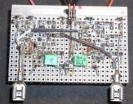
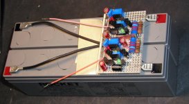
I found it particularly convenient to mount the board directly on batteries in this way.
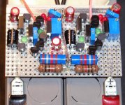
I like the small size of the board and it was actually easier for me to do it this way, then the previous one, when I had to look for all the parts and mods😉
The digital circuit will come in front of it and will be also powered from battery as well.
I like the small size of the board and it was actually easier for me to do it this way, then the previous one, when I had to look for all the parts and mods😉
The digital circuit will come in front of it and will be also powered from battery as well.
Attachments
Member
Joined 2002
Here's an interesting post regarding the sound of by pass cap used in TDA1543 http://www.diyaudio.com/forums/showthread.php?s=&postid=298592#post298592
Rudolf,
do you have any news about this I/V stage? I don´t trust my electronic skills enough to try the more advanced solutions, so the "easy to copy" really got my interest.
Michael
rbroer said:[BI'm just soldering a SE version that only needs a plus rail,
and uses cheap bjts. Cascodes on current source and common base transistor.
Will let you know how it sounds, and maybe post it as well since I'm using vero-board this time, in stead of pcb,
so it should be easy to copy. [/B]
do you have any news about this I/V stage? I don´t trust my electronic skills enough to try the more advanced solutions, so the "easy to copy" really got my interest.
Michael
Rudolf, that's great... how does it compare it with passive I/V?
If I understand correctly the supply is 15V, right?
If I should use a battery for powering it do I risk clipping?
Cheers
Andrea
BTW What's the color of the leds?
If I understand correctly the supply is 15V, right?
If I should use a battery for powering it do I risk clipping?
Cheers
Andrea
BTW What's the color of the leds?
OK,
In fact, my question was for the schematic on the 1st page. The voltage on the input is less obvious on it
Rudolf: I didn't find the LM334 locally, can I use a Jfet with a resistor?
In fact, my question was for the schematic on the 1st page. The voltage on the input is less obvious on it
Rudolf: I didn't find the LM334 locally, can I use a Jfet with a resistor?
On the Super Pair schematic the idac voltage is 2*Vled.
The answer to your question about the 1541 is already given at post #21, check it out.
Cheers
Andrea
The answer to your question about the 1541 is already given at post #21, check it out.
Cheers
Andrea
Rudolf, you said that in order to use this IV with a TDA1541, we should replace the 2 red leds with a 1N4148 one.
This would have as a consequence to put the input at 0.7V (if I'm right...) Shouldn't the input be at virtual ground, with a 1541?
This would have as a consequence to put the input at 0.7V (if I'm right...) Shouldn't the input be at virtual ground, with a 1541?
It would be very nice if Rudolf could put the schematics adopted for TDA1541A here.
Any chance Rudolf?
Bartek
Any chance Rudolf?
Bartek
Just my 2cts...
I think that Rudolf was wrong when he told to replace the 2 red leds with a 1N4148 diode, to use this I/V with a TDA1541A.
On it's previous I/V (the one with the DC servo), the difference between the TDA1543 version and the TDA1541A version was the replacement of the 2 leds by a 1N4148 diode. But there, the input voltage was 1 diode drop below the input transistor's base (so, 1 diode drop below 1 diode-> virtual ground)
Here, the input voltage is the same (approx.) as the voltage at the input transistor's base. So putting a diode on it would put the input at 0.7V.
To have a virtual ground on the input, the input transistor's base should be at 0V. But I don't know the consequence of tying it directly to ground. Maybe it's good, maybe not.
I hope that Rudolf will tell us if I'm right, or correct me.
zygibajt said:It would be very nice if Rudolf could put the schematics adopted for TDA1541A here.
Any chance Rudolf?
Bartek
Not sure what you mean Bartek ?
What updated schematics ?
😕
Sorry for being unclear.
If you would be so kind to tell me (us) what exactly should be changed to make this circuit work with TDA1541A.
I tried to figure this out from two of your previous 'LESS SIMPLE I-V stage (for TDA1543 an TDA1541) circuits.Trying to catch the diffrances and adopt it to this one but I guess I got lost ,and I'm not 100% sure what it should look like.
Bartek
Attachments
rbroer said:
Not sure what you mean Bartek ?
What updated schematics ?
😕
Are you ignoring me? 😡
zygibajt said:Sorry for being unclear.
If you would be so kind to tell me (us) what exactly should be changed to make this circuit work with TDA1541A.
I tried to figure this out from two of your previous 'LESS SIMPLE I-V stage (for TDA1543 an TDA1541) circuits.Trying to catch the diffrances and adopt it to this one but I guess I got lost ,and I'm not 100% sure what it should look like.
Bartek
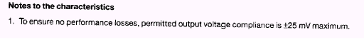
I mistakenly mentioned replace the two red LEDs with a diode in post #21. This is true for the non-super pair I/V, but here we need a voltage around 0V on the base of the PNP.
On my TDA1543 board I measured 3.000V on the base and 2.965V on the collector of the PNP
I'll leave it up to you to compensate these mV's.
Let us know how it sounds 😎
zygibajt said:Sorry for being unclear.
If you would be so kind to tell me (us) what exactly should be changed to make this circuit work with TDA1541A.
I tried to figure this out from two of your previous 'LESS SIMPLE I-V stage (for TDA1543 an TDA1541) circuits.Trying to catch the diffrances and adopt it to this one but I guess I got lost ,and I'm not 100% sure what it should look like.
Bartek
rbroer said:
I mistakenly mentioned replace the two red LEDs with a diode in post #21. This is true for the non-super pair I/V, but here we need a voltage around 0V on the base of the PNP.
On my TDA1543 board I measured 3.000V on the base and 2.965V on the collector of the PNP
I'll leave it up to you to compensate these mV's.
Let us know how it sounds 😎
Hi Rudolf,
Sorry to diverge slightly.
WRT comparisons of the "super pair" folded cascode I-V and
the single rail version, I noticed you are running about 16mA
through super pair and about 3.5mA through the single rail
version.
I think the differences you are hearing between these two
topologies is more due to current than topology type 🙂
I suggest running equal currents and re-compare 😎
Regards,
Terry
- Status
- Not open for further replies.
- Home
- Source & Line
- Digital Source
- "Super-Pair" I/V for TDA1543