Terry Demol said:
Hi Rudolf,
Sorry to diverge slightly.
WRT comparisons of the "super pair" folded cascode I-V and
the single rail version, I noticed you are running about 16mA
through super pair and about 3.5mA through the single rail
version.
I think the differences you are hearing between these two
topologies is more due to current than topology type 🙂
I suggest running equal currents and re-compare 😎
Regards,
Terry
Terry, you seem to know how a super pair works (at least better than I do)
Do you know if there is a solution to set Vbe to zero?
BTW, where can I learn more about the super pair?
Bricolo said:
Terry, you seem to know how a super pair works (at least better than I do)
Do you know if there is a solution to set Vbe to zero?
BTW, where can I learn more about the super pair?
Bricolo,
If there is 0V between base and emmiter (Vbe), the transistor
is turned OFF. I think what you mean is how to get DAC
IP point to GND, is that what you mean?
Terry
Bricolo wants to use this circuit with a TDA1541 (and I must say that it's what I want to do also..), so the Idac point should be set close to zero.
I guess that grounding the base of the transistor that now has 2 leds in series to gnd can bring the desired node to 0V, but are there risks in doing that?
Cheers
Andrea
I guess that grounding the base of the transistor that now has 2 leds in series to gnd can bring the desired node to 0V, but are there risks in doing that?
Cheers
Andrea
Terry: yes
Andrea: it's not as simple as this. that's why I asked this question to Terry.
The problem is that the voltage between Q2P's base and Q2N's emitter (this is what I called the "Vbe of the super-pair" in my previous post) isn't exactly zero (my sims show -50mV)
And 50mV is too much, according to the TDA1541A's datasheet.
Grounding Q2P's base directly would pose no ptoblem itself, I think (but I'm really not sure) that it would even be better, since the impedance of the voltage source is exactly zero (in fact, the voltage of the voltage source is also zero, if you compare it to the leds that have something loke 3V and 10R)
But you'll have those 50mV on the input 🙁
I see no solution yet. Using a pot (the wiper on Q2P's base, and the 2 other legs on V+ and V-) we would be able to set the input to zero. But the impedance will be high between the base and ground. A small value pot would draw too much current...
Maybe Terry or someone else has a solution
You could use a regulator between the rails (say a TL431 or a LM317 but I'd prefer the former) and use a pot to trim the offset (varying the regulator voltage).
Cheers
Andrea
Cheers
Andrea
Bricolo said:Terry: yes
Andrea: it's not as simple as this. that's why I asked this question to Terry.
The problem is that the voltage between Q2P's base and Q2N's emitter (this is what I called the "Vbe of the super-pair" in my previous post) isn't exactly zero (my sims show -50mV)
And 50mV is too much, according to the TDA1541A's datasheet.
Maybe Terry or someone else has a solution
OK, you can not use a single supply for TDA1541. You need
a neg supply to set up a current source to bias N channel
GBS BJT on.
Use a diode or diode connected BJT with cathode to gnd to lift the
GBS BJT's base 0.7V above ground. It's emmiter will then be at 0V.
Put a current trim from diode to + supply and this can be fine
tuned if desired to get virtual GND within 10mV of GND.
OK now a simple "dumb" question for you, how do I post
a schematic here?
Cheers,
Terry
There is an attach file window (right above Submit Reply button). Valid file extensions: gif jpg png txt zip bmp jpeg.
Terry Demol said:
OK, you can not use a single supply for TDA1541. You need
a neg supply to set up a current source to bias N channel
GBS BJT on.
Use a diode or diode connected BJT with cathode to gnd to lift the
GBS BJT's base 0.7V above ground. It's emmiter will then be at 0V.
Put a current trim from diode to + supply and this can be fine
tuned if desired to get virtual GND within 10mV of GND.
OK now a simple "dumb" question for you, how do I post
a schematic here?
Cheers,
Terry
I will use a neg supply! I'm talking about the circuit Rudolf posted on this thread (not the single supply one, the folded cascode one!)
To attach a file, when you're typing your message there's a "Browse" button, just over the "submit Reply" one. Attach a file with it. As peter said, not all file formats are accepted. You have to limit the graphic and file size too, I think it's 800*600 and 100kb.
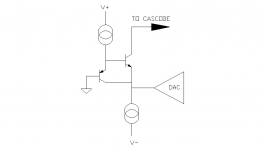
I'm not sure I understand your answear. The reference schematic is this one, what modifications should be done to put I-dac on 0V?
Attachments
Bricolo said:
I will use a neg supply! I'm talking about the circuit Rudolf posted on this thread (not the single supply one, the folded cascode one!)
To attach a file, when you're typing your message there's a "Browse" button, just over the "submit Reply" one. Attach a file with it. As peter said, not all file formats are accepted. You have to limit the graphic and file size too, I think it's 800*600 and 100kb.
I'm not sure I understand your answear. The reference schematic is this one, what modifications should be done to put I-dac on 0V?
Hi Bricolo,
OK, all is clear.
To move virtual gnd to 0V just omit D2, D3 and R1. Base of Q2P
will then be grounded. Emmiter Q2P = +0.7V so Emmiter Q2N
goes back to 0V.
Note however that the VBE of Q2P and Q2N will not be
exactly the same due to different voltages across them.
However this will be cancelled out to a degree because
Q2P is run at much less current than Q2N.
My guess is that it will be within 20mV of gnd.
Cheers,
Terry
In my simulations, it's not within 20mV of ground, but rather 50mV
And the TDA1541A has a voltage compliance of 25mV 🙁
That's why I wanted to be able to ajust it precisely.
BTW, what's the currenct source between Q2P's emitter and V+, on your schematic?
And the TDA1541A has a voltage compliance of 25mV 🙁
That's why I wanted to be able to ajust it precisely.
BTW, what's the currenct source between Q2P's emitter and V+, on your schematic?
Bricolo said:In my simulations, it's not within 20mV of ground, but rather 50mV
And the TDA1541A has a voltage compliance of 25mV 🙁
That's why I wanted to be able to ajust it precisely.
Would it not be OK to have resistor chain between the rails, two fixed values to the rails with a variable one in the middle that covers the critical area with a cap from the wiper of the trimmer to earth to deal with any noise and a connection base of Q2P also to the wiper of the trimmer.
This is a very simple possible solution - are there any drawbacks ?
Of course it will need to be carefully set initially but I think it should be OK if the cct's are left switched on.
Terry Demol said:WRT comparisons of the "super pair" folded cascode I-V and
the single rail version, I noticed you are running about 16mA
through super pair and about 3.5mA through the single rail
version.
I think the differences you are hearing between these two
topologies is more due to current than topology type 🙂
I suggest running equal currents and re-compare 😎
The one posted in the thread is using initial values from the simulator.
The one in my cd player is actually 10mA Terry.
Didn't observe much improvement though...

mikelm said:Would it not be OK to have resistor chain between the rails, two fixed values to the rails with a variable one in the middle that covers the critical area with a cap from the wiper of the trimmer to earth to deal with any noise and a connection base of Q2P also to the wiper of the trimmer.
This is a very simple possible solution - are there any drawbacks ?
Of course it will need to be carefully set initially but I think it should be OK if the cct's are left switched on.
Finally a solution 😀
I would do something like this (capacitor from wiper to ground can be added):
Attachments
That's what I proposed some posts before (except from the 47R resistor and the cap)
But this would have a much higher impedance voltage reference than the diodes. Isn't this a problem?
But this would have a much higher impedance voltage reference than the diodes. Isn't this a problem?
Bricolo said:That's what I proposed some posts before (except from the 47R resistor and the cap)
But this would have a much higher impedance voltage reference than the diodes. Isn't this a problem?
Bricolo,
Stop simulating, stop worrying, start soldering

What is the problem with 47R at base of Q2P?
Cheers,
Terry
Terry Demol said:
Bricolo,
Stop simulating, stop worrying, start soldering
What is the problem with 47R at base of Q2P?
Cheers,
Terry
Tell 'm Terry

For your info, it does simulate fine, for as much as we can rely on distortion numbers from a simulator...
Real life measurements showed about 35mV for VBC(Q2P)
Terry Demol said:
Bricolo,
Stop simulating, stop worrying, start soldering
What is the problem with 47R at base of Q2P?
Cheers,
Terry
I don't know what's wrong with it.
My question was if it is better to have a low impedance voltage reference from Q2P's base to ground.
I think it is (but maybe you have another opinion), so the voltage divider isn't optimal 🙁
Bricolo said:
I don't know what's wrong with it.
My question was if it is better to have a low impedance voltage reference from Q2P's base to ground.
I think it is (but maybe you have another opinion), so the voltage divider isn't optimal 🙁
Bricolo,
47R is absolutely OK from base to gnd. Believe me! 🙂
Now build that damn thing

Cheers,
Terry
Terry Demol said:
Bricolo,
47R is absolutely OK from base to gnd. Believe me! 🙂
Now build that damn thing
Cheers,
Terry
don't worry! I'm designing the layout for it, on a veroboard. I hope It will be finished soon
- Status
- Not open for further replies.
- Home
- Source & Line
- Digital Source
- "Super-Pair" I/V for TDA1543