Bricolo,
I misted some couple of posts here.Is this a final solution for TDA1541A?
I'm ready to try it out.
Bartek
I misted some couple of posts here.Is this a final solution for TDA1541A?
I'm ready to try it out.
Bartek
Bricolo said:
don't worry! I'm designing the layout for it, on a veroboard. I hope It will be finished soon
Hi Bricolo,
I'm not very keen on using veroboard for proto's especially
high speed stuff like unfiltered PCM.
I usually just start with a solid copper covered PCB and
neatly xmas tree everything on top. Depending on circuit,
a double sided solid copper covered PCB with PS rails cut
into one side with a dremel or hacksaw also works well.
With this method you get a good low Z ground to decouple to.
I also find it quicker than vero.
YMMV.
Cheers,
Terry
Terry Demol said:
Hi Bricolo,
I'm not very keen on using veroboard for proto's especially
high speed stuff like unfiltered PCM.
I usually just start with a solid copper covered PCB and
neatly xmas tree everything on top. Depending on circuit,
a double sided solid copper covered PCB with PS rails cut
into one side with a dremel or hacksaw also works well.
With this method you get a good low Z ground to decouple to.
I also find it quicker than vero.
YMMV.
Cheers,
Terry
Do you mean point to point, with the components glued on a copper plate?
BTW, maybe we don't have the same idea about what a veroboard is. I'm not sure I'm using the right name, I'm talking about the prototype board with the pads around the holes, not the one with the stripes.
I was planing to use a double side one, with a ground plane on the components side.
Bricolo said:
Do you mean point to point, with the components glued on a copper plate?
BTW, maybe we don't have the same idea about what a veroboard is. I'm not sure I'm using the right name, I'm talking about the prototype board with the pads around the holes, not the one with the stripes.
I was planing to use a double side one, with a ground plane on the components side.
No glue, you don't need it. Just use ground references such decoupling caps to hold it off the gnd plane, is usually enough.
Cheers,
Terry
Terry Demol said:
No glue, you don't need it. Just use ground references such decoupling caps to hold it off the gnd plane, is usually enough.
Cheers,
Terry
OK, it seems similar to the "dead bug style" Thorsten explained once
But, what's wrong with veroboards?
Hi guys!
Mr Broer,
I have few questions..... I have tda1543 and cs8412 based dac without reclocking and with passive i/v conversion. It is running at 7V power supply.
I am reconsidering to try some things at the output of the dac. Maybe this circuit would do the thing fine?
first:
If I get this right the resistor form pin 7 to ground is 1k2 if the power supply of the tda1543 is +5V.
second:
What type did U use for the diode in power supply regulator near ZTX690B and which type is Q4?
third:
Pot 1k is a potentiometer (near RSOA1A 56R) right? Could U tell me please how to adjust it (adjustement procedure like Jean-Paul asked in post #30- or at least where could it be found (Iknow how to use Search engine but don't now what to look for 🙁 ).
Fourth:
Is this much better than using passive i/v?
(Peter Daniel - what do U say- do U use it right now?).
thanks
daniel
Also - do I need to make any changes if I would like to use this circuit with TDA1543 with power supply of 7V?

thanks
p.s. which circuit is the best for tda1543; super pair on jocko's simple one.....?😀
daniel
thanks
p.s. which circuit is the best for tda1543; super pair on jocko's simple one.....?😀
daniel
No need to make changes also with different supply voltages.
As for the best circuit...try yourself and let us know!
Cheers
Andrea
As for the best circuit...try yourself and let us know!
Cheers
Andrea
o.k. thanks...
I have figured the answer to my first question in meanwhile.
- I don't need no resistor on pin7 of the TDA chip. Right?
Could anyone answer my 2nd to 4th question (Mr. Rbroer?) 
thanks in advance
daniel
I have figured the answer to my first question in meanwhile.
- I don't need no resistor on pin7 of the TDA chip. Right?
Could anyone answer my 2nd to 4th question (Mr. Rbroer?)
thanks in advance
daniel
sparkle said:o.k. thanks...
I have figured the answer to my first question in meanwhile.
- I don't need no resistor on pin7 of the TDA chip. Right?
daniel
You still need something between pin 7 and Gnd to set the bias current for the TDA1543... this pin stays at about 2.2V and its output current, (doubled) is the Ibias of the Dac.
You can leave the old value for the resistor, but don't leave it out!
Cheers
Andrea

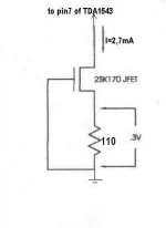
This is the CCS proposed by Stefanobilliani, but the current drawn is too high , since Ibias has a maximum of 5 mA and Ibias = 2* Iref.
I'd suggest the use of a CCS with a current of 1.5-2mA
Cheers
Andrea
I'd suggest the use of a CCS with a current of 1.5-2mA
Cheers
Andrea
When you use this current source is important to note the voltage across the resistor and choose the resistor by consequence , since 0.3V is a "typical" value and vary between devices.
Hi guys!
Can someone suggest me substitutions for ZTX690, ZTX790, 2SA1085E and 2SC2547E.
They are difficult to find. Maybe some BC or BD types?
I supose that BC549C and BC557B would substitute 2SA1085 and 2sc2547????
thanks
daniel 🙁
Can someone suggest me substitutions for ZTX690, ZTX790, 2SA1085E and 2SC2547E.
They are difficult to find. Maybe some BC or BD types?
I supose that BC549C and BC557B would substitute 2SA1085 and 2sc2547????
thanks
daniel
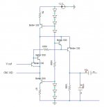
🙁12.7V version for 1543/3 ?
I worked out this version for my 1545 that I think will work for 1543 aswell.
I wanted something that will run from a 12 volt battery
As I need a cap on the o/p anyway to protect my transformer volume control from even the tiniest amount amount of DC I just settled on a big offset at the output.
It measures very well in simulation.
What do the experts think ?
does it pass ?
any drawbacks ?
O.K. here we go,
2sa970 <=> 2SA1085
2sc2240 <=> 2sc2547
ztx690 <=> 2sd1624
ztx790 <=> 2sa1797
I would try these transistors and let You know...
regards
daniel
2sa970 <=> 2SA1085
2sc2240 <=> 2sc2547
ztx690 <=> 2sd1624
ztx790 <=> 2sa1797
I would try these transistors and let You know...
regards
daniel
- Status
- Not open for further replies.
- Home
- Source & Line
- Digital Source
- "Super-Pair" I/V for TDA1543