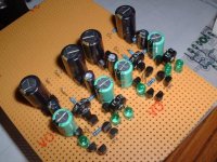
The one I built has some small differences with Rudolf's schematic (mostly because I had difficulties to find some parts)
-the 1st caps are 680uF (the green ones will be changed to 470uF when they'll arrive)
-transistors are BC550C BC560C, except for the 2 japaneese that are 2Sc2547 and 2Sa1085
-the 2nd CCS is cascoded with a J309
-I/V resistor is a Dale CMF-55 1.24kR
-output cap (LP filter) is a 1nF styroflex
-the LM334 is replaced with a J309+110R (5mA) (the i/V is 100% discrete now 😎 )
-it will be used with a TDA1541; so D2 and D3 are replaced with a 47R resistor. Maybe I'll add a 100uF on it
Attachments
Got it, tomorrow I'll phone my eye doctor for an exam...
I read (and of course bought and soldered) 80R instead of 180R for RSI2
I read (and of course bought and soldered) 80R instead of 180R for RSI2
Hi,
I've built the IV some months ago, but it didn't work properly. After a couple of days trying to have ot work, it layed somewhere until today.
Now, I spent all the afternoon with it, still trying to make it work. But nothing helped 🙁
I still have a big (3.2V) offset at the output, the pot seems to be here to tune the offset, but with the pot at 100% (1k) there's a 3.2V offset
With the pot at 0, the leds shut down, and the offset goes up to 5V
But never zero inbetween
Does anyone have an idea, please?
OK, I found my error: I put the BC550 instead of the 2SA1085 and the 2SA1085 instead of the BC550
It certainly couldn't work this way 😀
But now, this thing oscillates like mad 😡
At powerup, it's 32MHz 3Vpp
When I touch some pins with a screwdriver, it becomes 64MHz 300mVpp
And back to 32MHz 3Vpp when I touch some over pins.
The oscillation even "goes back" to the psu, it's clearly visible on it. (my psu is made of 6 9V cells in series) I assume that the regulator isn't effective anymore at such frequencies, and that the caps aren't neither (I only use lytics, like in the schematic, no bypassing)
It seems VERY sensitive! When I touch the board, the DC offset changes. When I move my hand near the board, it changes too. I can even see the curve move on the scope when I'm placed 1 meter away and move my arms 😱
The DC offset isn't stable either, sice it changes with my hand's position it's hard to tune it with the pot. But even worse, if I switch it off and on again, the DC changes also a lot (a few hundred of mV)
One problem is solved, another shows up 🙁
have a look here...
http://www.diyaudio.com/forums/showthread.php?s=&threadid=29750
my 12.7V version oscilated until I added the caps as shown.
after that it sounded great.
I hope mod works on your cct which I know is slightly different.
mike
http://www.diyaudio.com/forums/showthread.php?s=&threadid=29750
my 12.7V version oscilated until I added the caps as shown.
after that it sounded great.
I hope mod works on your cct which I know is slightly different.
mike
Hi, thank you for your post
Can you detail the symptoms your version had, please?
Did you try various cap values, and various positions, to obtain something stable?
Do you use a pcb? I'm on a veroboard, I can post the layout if you want
Can you detail the symptoms your version had, please?
Did you try various cap values, and various positions, to obtain something stable?
Do you use a pcb? I'm on a veroboard, I can post the layout if you want
Bricolo said:Hi, thank you for your post
Can you detail the symptoms your version had, please?
Did you try various cap values, and various positions, to obtain something stable?
Do you use a pcb? I'm on a veroboard, I can post the layout if you want
Well - it oscillated
blank vero board - the original design was on doudle sided with an earth plane so this might explain the problem
I suggest you try the mod using the values I did and if this does not fix it then we can think a bit more
good luck
mike
p.s. but from memory the values were not that critcal
ok I'll try that. I have some cheap 0.1uF filp caps laying around.
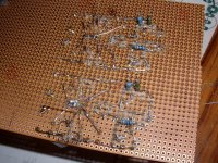
Did you place the caps as close as possible to the transistors (less than 5mm), or did it work with moderate traces length?
Here's my layout for the veroboard (IV resistors and capacitor aren't shown)
Did you place the caps as close as possible to the transistors (less than 5mm), or did it work with moderate traces length?
Here's my layout for the veroboard (IV resistors and capacitor aren't shown)
Attachments

When I said the values were not that critical, I did not mean that 100 times more would be OK...
0.1uF will almost certainly roll off the treble.
I would think the 330pF - 1000pF ( 1nF ) would be worth trying.
I would solder them onto the bottom of the board.
mike
0.1uF will almost certainly roll off the treble.
I would think the 330pF - 1000pF ( 1nF ) would be worth trying.
I would solder them onto the bottom of the board.
mike
Bricolo said:BTW, what's this 0.099R resistor for, in your scematic?
Ignore that, it's just there to help b2spice run.
OK, I'll try with some caps tomorrow
I just tested without the super pair (shorted the base and emitter of the "control" transistors), the oscillation changed, was smaller (50 to 100mV) and at a lower frequency (300kHz) but was still here 🙁
So it's not (only) the super pair that causes this behaviour
I'll also test the board at scool tomorrow, if I have the time. I don't know why but many things I test at home do like to oscillate... my next project will be a DIY faraday cage 😀
even when I just place the probe some cm away from the board, I can see oscillations at nearly the same amplitude
what can cause this?
what can cause this?
Bricolo said:even when I just place the probe some cm away from the board, I can see oscillations at nearly the same amplitude
what can cause this?
The board is acting as a RF transmitter
Are your supplies properly decoupled ?
If not, You could try using those 0.1uF close to the where the rails connect with the cct - with leads running to the earth.
beyond this - perhaps rbroer can help
http://www.diyaudio.com/forums/member.php?s=&action=getinfo&userid=1750
mike
The power supply (for testing) is made of 6 9V cells in series
No decoupling at all for the momment, only the lytics shown on rudolf's schematic. (and the ceramic you adviced on the 3 transistors)
But I tested at achool, and with a bench power supply it also oscillated
No decoupling at all for the momment, only the lytics shown on rudolf's schematic. (and the ceramic you adviced on the 3 transistors)
But I tested at achool, and with a bench power supply it also oscillated
Bricolo said:The power supply (for testing) is made of 6 9V cells in series
No decoupling at all for the momment, only the lytics shown on rudolf's schematic. (and the ceramic you adviced on the 3 transistors)
But I tested at achool, and with a bench power supply it also oscillated
If you are not using very low or ultra low impedance caps the 0.1uF's might help.
mike
- Status
- Not open for further replies.
- Home
- Source & Line
- Digital Source
- "Super-Pair" I/V for TDA1543