Barniboy - your notes on the 2nd BW crossover to mitigate the midrange-horn notch are very, very interesting. Thanks for the publication.
Thanks for posting Barniboy, lots of interesting info to digest. I had shortly after my post come accross the BF 37 as the SB36WBAC21-8 are relatively expensive in the UK so I had a look for alternatives. The BF 37 is only £7.50 each on CPC. Its very interesting that you got the FRS 5 as high as 2kHz as this has ~+10dB sensitivity over the 1/1.5" drivers so for me would probably be a better choice. I will have a read through all your documents, I don't think I'm well ahead at all considering you have actually built your horn.
The study of blocking S1 and S2 is very interesting as this would suggest the taps do not have to be as close to S1 which is beneficial for HF response and would instead be constrained to just been within a quarter wavelength of each other.
Addressing some of your points:
1) I haven't tried to the extend the LF response of the mid-ranges but for small drivers the ideal rear chamber volume is often much smaller than even the small cans used. In my first MEH I just paper mache the back of the basket to make as small as possible rear chamber as this is what the simulations indicated was ideal. https://www.diyaudio.com/community/threads/bm-d446-on-ph-4220.335062/
2/3) perhaps we need to move beyond bandpass chambers for the mid-ranges to something like a horn with phase plug and area expansion function if we want to move up in frequency here are a couple of threads that might be of interest:
https://www.diyaudio.com/community/threads/renkus-heinz-1996-unity-horn-patent-us5526456a.360404/https://www.diyaudio.com/community/threads/suggestions-on-theory-behind-co-entrant-horns.4602/
In reply to Kipman, post 2422:
(Ad. blocking S1 and S2) Yes, I was quite relieved to discover that the waves seems to bounce-off directly from S2, going only forward in the horn, regardless of S1 being open or closed or even if the length S1-S2 does not exsist. In particular because the Danley patent goes to great lengths in explaining about some waves going both back in the horn and some forward. The backward wave being reflected at S1, and then interfering with the waves going forward.
A good thing that does not seem to happen.
(Ad. 1) The "Isobarik" thing was just a suggetion. But it would be interesting to make a simulation using data of two closely combined units to see if that makes any good. Or else, how about a Linkwitz transform, anyone ?
(Ad. Quarter wavelength) You mean acoustically, counting all delays, including drivers ? IMHO the MF and HF drivers, ideally, should be in counterphase (notch) at the desired cross-over frequency. This, and the mechanical layout of a MEH, makes the HF "90° lagging" and the MF "90° leading", constituting a combined 180° out-of-phase situation. Then you apply the opposite, a "standard" 2nd order Butterworth filter (HF 90° "leading") and MF (90° "lagging") to both units and, heureka !, end-up with no notch and in-phase units over the cross-over region.
In fact, this is the oldest trick in the HiFi book: A two-way speaker with a bass-mid woofer and a tweeter, plus a 2nd order Butterworth filter.
Oops, a BW2 leads to HF and LF being 180° out-of-phase, doesnt it ? Well, reverse the connections to ONE of the speakers. and you're done !
A good many two-way speakers are made like this, some fine-tuned by stepping-back the tweeter to account for driver delays.
(Ad. 2/3) The links you posted are well known to me. But please observe that enormous S2 ports are displayed. Involving ducts and "horns" at S2 will do just that , I guess. IMHO thats not what we need, because:
The HF driver and S1 is at one end, remember. Waves originating from here will pass thru the entire horn, passing S2. So S2 must be "acoustically invisible" to the HF waves. Generally, this is the case if the S2 longest dimension is shorter than one wavelength of the highest frequency.
Thats pretty small, in fact the 14mm ports of the Rashorn and Cosyne is just on the border.
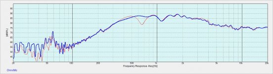
Here is a measurement of my AMT-1 + 2x 3FE22 MEH with both mid and HF in parallel.

So what you say above is to use 2nd order BW at 1468 Hz (the cursor is a bit off at the export, idk why) and that should give me perfect phase alignment? I need to try that.
So what you say above is to use 2nd order BW at 1468 Hz (the cursor is a bit off at the export, idk why) and that should give me perfect phase alignment? I need to try that.
Yes, in theory you should see a "phase restablishment" at the XO frequency 1471 Hz above.
However, I think you should "level" HF and MF responses prior to the above measurement. That may shift your notch frequency a little bit.
Also, after levelling. make two measurements, one for each driver individually. Just to see the extent of overlap.
If the overlaps are substantial, the above should hold fairly well.
However, if not. e.g. each driver slopes at 1471 Hz already, there are "other filters" in there, and you should not expect much.
Perhaps now some may understand why I am so keen on extending the bandwidth of the MF as much as possible ?
Empirically disruptions in the horn geometry further from the throat seem to have less effect on high frequencies so perhaps these coenterant horns are not as bad as they look?In reply to Kipman, post 2422:
(Ad. 2/3) The links you posted are well known to me. But please observe that enormous S2 ports are displayed. Involving ducts and "horns" at S2 will do just that , I guess. IMHO thats not what we need, because:
The HF driver and S1 is at one end, remember. Waves originating from here will pass thru the entire horn, passing S2. So S2 must be "acoustically invisible" to the HF waves. Generally, this is the case if the S2 longest dimension is shorter than one wavelength of the highest frequency.
Thats pretty small, in fact the 14mm ports of the Rashorn and Cosyne is just on the border.
Perhaps also the exits of the midrange horns could be 'hidden' from the HF driver, there is some discussion here about mass loaded transmission lines and tap shapes that effect the compression driver less:
https://www.diyaudio.com/community/threads/increasing-loading-of-midbass-in-synergy-horn.342329/perhaps I will have some time to actually look into this when I clear some other projects.... (AKABAK3 makes testing such things way less laborious!).
Pelanji I got 1.27kHz acoustic crossover out of these mid drivers so your result looks plausible.
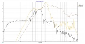
Yes, I think it needs a bit more attention, this is all three plots in one chart. I tried to make the crossover in XSIM and it makes some nice on axis summation. My first DSP crossover for this was at 1 kHz and a little delay compensation - worked fine as well (on axis). There is quite a nice overlap ca 700 - 1400 Hz available, that gives some freedom with DSP and might work also as passive.

In reply to Pelanj, post 2429:
Thanks for posting the frequency response chart.
It is clearly seen, that the large diaphragm volume of the Faital 3FE22's is shunting output to S2, decay is from about 1 KHz.
With your midrange already in decay at the XO frequency "other filters" are in there and the "BW2 trick" will be more subtle.
In your post 2425 you used the words "....should give me perfect phase alignment".
Well, needless to say, I hope, the "BW2 trick" will only do that "perfectly" if both speakers have infinite and equal f-responses.
That will probably never happen, we have to be pragmatic about the issue, but still, the "BW2 trick" can bring us a long way and is, I believe, sound engineering.... ahem 🙂
But just as interesting is that the chart in post 2429 shows both drive units largely within the minimum-phase regions.
That means that prudent use of parametric equalising (e.g. starting with reducing the yellow curve about 5 db) to equalise the amplitude responses
will, also equalise the phase responses and thus get us a little bit closer to your "perfect phase alignment", using BW2.
In the case above, however, I am not convinced that "prudent equalising" will be to lift the yellow curve 20 db at 2 KHz.
But perhaps dumping the Faitals and use 4 pcs. 2" units could do something ? Depends on the size/position of S2 as well, of course.
Digital delays will probably upset the minimum-phase property, though. I am not sure about that.
In reply to Kipman, and the link, post 2427:
Ad. Empirically... I do not entirely agree. I have measured my MEH with and without the LF ports covered by masking tape, and there IS a difference. But again, pragmatism must rule and the question is if it matters much. Maybe I get some time to revert here with some measurements.
Ad. Perhaps also... I think the link you posted is about the LF tabs. It is suggested to use a mass loaded 1/4 wavelegnth duct to "force feed" the LF ports of a MEH. This involves a long duct that will delay the LF drivers "out of vicinity". This will upset the possibility of "phase matching" the MF and LF, as dicussed above, perhaps thus upsetting important issues for HiFi. PA is quite another issue, I think.
I think I should rather move the taps further away from the throat as I would like to have a lower crossover anyway. Thanks for the analysis, it is all beginning to make sense to me.
Hi Barniboy, i found masking tape, even thick duct tape, didn't block port action very much on any of my MEH builds .In reply to Kipman, and the link, post 2427:
Ad. Empirically... I do not entirely agree. I have measured my MEH with and without the LF ports covered by masking tape, and there IS a difference. But again, pragmatism must rule and the question is if it matters much. Maybe I get some time to revert here with some measurements.
I resorted to thin sheet steel which worked very well.
Also have to say that the port to throat distance showed a notch as expected, wherever i placed the ports.
I've done the same kind of things, open CD hole, blocked CD hole, plate blocking closer to ports, etc.....but never with the precision and care you posted.
I have no idea why your particular build isn't showing a more pronounced notch. But i appreciate the intrigue.... 🙂
In follow-up to my post 2430 "Ad. Empirically..." :
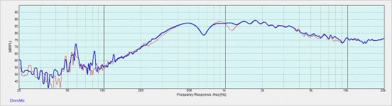
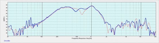
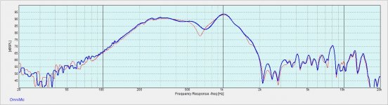
Gee, I managed to find a measurement from long ago of the raw responses.
The red and orange curves show the HF response with masked and open ports, drivers fitted.
It must have been ALL ports I did, but I made no note of just that.
As one can see, there IS a difference, but not much.
Could be interesting to do it again to see if the MF or the LF ports dominates.
(the "notch" at 6KHz is driver-related, perhaps a defect, but it is there on other measurements I did.)
The yellow curve seems to indicate "there could have been more" and I torture myself by thinking that concentric ports could have brought a little bit ekstra output between 2 and 3 KHz. But then again, even with just 2" drivers it IS hard to make room close to S1. (1,5" drivers maybee...).
The green nearfield curve shows just a closed-box response (this meas. is including the rear cabinet). So the horn does'nt do much, only making drivers concentric. In my next horn, if ever, I would put S3 outside the main horn, perhaps as slots in the final flares.
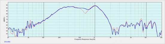
I don't think the tap hole frequency dips matter much as the driver responses fill in the holes. Attached is the tweeter response with the mid hole covered and the tweeter response with the woofer holes covered
Attachments
In reply to jrh0516, post 2434:
These are nice measurements you did.
Could you perhaps elaborate a little more about which is which (e.g. "Case1: Blue curve showing..., red curve showing... Case2: ...") ?
These are nice measurements you did.
Could you perhaps elaborate a little more about which is which (e.g. "Case1: Blue curve showing..., red curve showing... Case2: ...") ?
For reference my horn posts start around 2140 and 2145. The pictures have titles. The first 2 pictures are of the conventional tweeter Tymphany XT25TG30 measured at the horn mouth. First is with the mid hole covered the second is with the woofer hole covered. The third picture is all three drivers measured at 1 meter from the horn mouth.
In reply to jrh0516, post 2140-2145, 2434 and 2436:
Thanks for "carving it in marble" 🙂
So, there is quite a tweeter-dip from the S3 taps at ~650 Hz and a smaller from the S2 tap (you have only one ?) at ~1100 Hz.
Thats very interesting. Maybe I should do my measurements again, and give it more attention.
Surprising to see such S3-dip when these taps are quite far from the S1 tweeter.
This strengthens my belief, that my next MEH, if ever, should have S3 out of the main horn (but stil concentric).
So S3 taps are causing a dip in the tweeter response at ~650Hz but what will be playing in this range is the mid. Is there also a dip in the mid response?
~650Hz dip is almost 10db, very surprising if it is only from the tap(s). Is the measurement far field or mic very close up?
The measurements are at the horn mouth (nearfield) except for the last picture (this is the final horn) which is at 1 meter. There is a dip in the mid response. I also found I could change the dip by moving the S3 taps. The dips are a function of the chamber volume, location and maybe tuning (not tested) by reducing the volume between the driver and the tap I could reduce the magnitude, last picture.
Attachments
- Home
- Loudspeakers
- Multi-Way
- Suitable midrange cone, for bandpass mid in Unity horn