The difference between Unity and Synergy is rather mysterious. Reading the patent they seem to me to describe the same horn but the Synergy horn adds a way to do the crossover design.
About the number of midranges:
From the tweeter's point of view, the ports to the midrange do nothing good and some things bad. IMO, If adding more midranges doesn't help the SPL level that you'll ever use, you are only complicating things and degrading the tweeter's response and pattern. And the tweeter covers more octaves and in more audible regions than the midrange(s) will.
Last edited:
Basically this is correct...but perhaps not sufficient.The difference between Unity and Synergy is rather mysterious. Reading the patent they seem to me to describe the same horn but the Synergy horn adds a way to do the crossover design...
Here is an excerpt from the DSL patent (US8284976B2) that illustrates what the difference is:
So if you want to do a Synergy (rather than a Unity), you flatten the overall phase/group delay. How do you do that? The patent doesn't say, but Danley himself does in another forum:For comparison purposes, and to illustrate advantages attainable with the present invention, a prior art horn/driver sound reproduction system was modified according to aspects of the present invention. A three-way sound reproduction system, Model Number td-1, commercially available from Sound Physics Labs, Inc. of Glenview Ill., was tested for both frequency and phase response characteristics. The system employs a straight conical horn having a pyramidal shape. Referring now to FIG. 4, the frequency response curve 60 and phase response curve 62 are shown for the unmodified system. The system was then modified to relocate the drivers with respect to the horn and to replace the crossover with new electronics, in accordance with principles of the present invention and was tested under circumstances similar to the test shown in FIG. 4, with the result illustrated in FIG. 5. The frequency response curve 66 and the phase response curve 68 of FIG. 5 shows substantial improvement over the performance of the unmodified system indicated in FIG. 4.
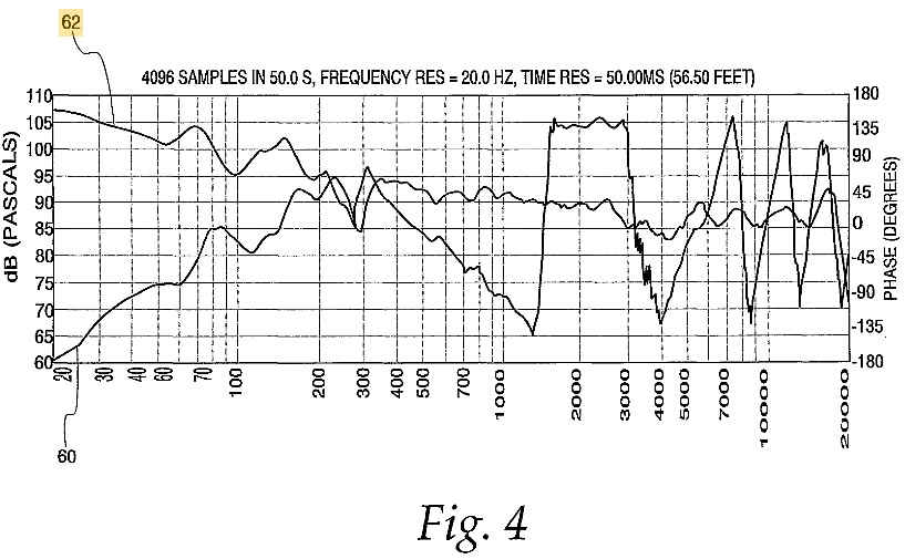
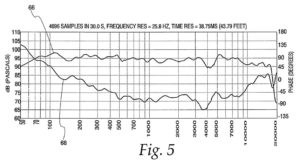
With the sound reproduction system according to principles of the present invention the phase shift indicated by curve 66 is much closer to 0 degrees. Also, in addition to the reduction in phase shift throughout the pass band, the amplitude curve 66 is smoother than the corresponding amplitude curve 60 for the unmodified system response indicated in FIG. 4. Thus, the modified according to principles of the present invention has much less group delay than the original, unmodified system, even though the same drivers and the same physical shell were used in both systems.
If you construct a "small Syn" then by definition, you're flattening the overall phase via proper selection of "crossover filters". If you don't flatten the phase and cross the lower frequency driver(s) below the first cancellation notch, i.e., the actual difference in patent claim from the Unity patent, then you've got a Unity--a poorer-sounding multiple entry horn....In reality, it, like all the Unity crossovers is not “integer slope” or butterworth, bessel shape etc but rather the shape is determined by the drivers amplitude and phase responses added together.
While it should be obvious that the acoustic summation is what matters, that has not stopped most from using their favorite processors product or to cause many to consider questioning the marketing status quo...
So the patent really is covering how to do the crossover itself, except that it doesn't actually patent the crossover itself--only the design choice to acoustically cross the lower frequency driver(s) below the first cancellation notch--something that happens in the Unity horn, too, since the acoustic output of the lower frequency driver
I've personally achieved this flatter phase response that Danley describes using a non-multiple-entry full-range horn (a Klipsch Jubilee 2-way), a DIY MEH based on the K-402 horn, and also Belle bass bin+AMT-1 tweeter...and the audible results pretty much describe to me what the difference is. But of course, two out of three loudspeaker types are not MEHs but rather reconfigured full-range horn-loaded loudspeakers with more than one horn aperture. So this "synergy effect" works pretty much as well with them, too, if you can get their horn centers within ~one wavelength (in my experience) at the center crossover frequency, use a zero phase shift or fractional order crossover filter set, and correct any relative delay mismatches via DSP crossover. The results sound much different--enough to where I can see Danley wanting to patent it (but how do you enforce such a patent claim...?)
Chris
Attachments

Last edited:
I am looking to build a small unity/synergy horn with response from 300, 400 or 500 Hz up and a crossover of between 1500 and 2000 Hz. I went through part of this thread but my head is spinning from info overload right now.
Would 4x Peerless 2.5" TC7FD04 work as a mids?
I saw the formula 2xFs/Qes should be around 530 for suitable drivers. This 2.5" fullrange driver has Fs=202, Qes=0.88 so it is slightly lower at 469 but still in the ballpark..
What results could I expect from this driver? Where can I expect to high and low pass these drivers? Is its 1mm xmax sufficient?
I want to build a horn for hifi use so high Spl is not needed. I plan to not use a compression driver but a xt25 ring radiator tweeter and cross over to two Dayton 10" classic woofers, one above and one below the horn.
I have easy access to Peerless drivers. Most other things are hard to get in Thailand and local stuff always comes without T/S parameters.
Another thing that still confuses me after hours of reading.....what is the difference between a Unity and a Synergy horn? It seems many people use the terms interchangeably but I know they are not the same.
If you'd like to save some time, I'm selling Unity horns that fit the bill:
"Unitized" Image Control Waveguide
"...acoustically cross the lower frequency driver(s) below the first cancellation notch--something that happens in the Unity horn, too, since the acoustic output of the lower frequency driver cannot produce sufficient SPL inside its first cancellation notch frequency band. "
Right, hence that's prior art done in then already marketed Unity horns. So how patented?
Right, hence that's prior art done in then already marketed Unity horns. So how patented?
what is the difference between a Unity and a Synergy horn?
Very little - they have essentially the same topology. CoEntrant, Unity and Synergy are just marketing names for different multiple entry horn loudspeaker products.
See the "Multiple entry horn" section on the page linked below for further background information:
Horn loudspeaker - Wikipedia
What do you guys think about this sim?
You should really be using the real-time Hornresp Multiple Entry Horn Wizard tool, rather than just simulating the mid-frequency drivers in isolation without taking the effect of the compression driver into account. The interactions between the high- and mid- frequency drivers are complex. The overall performance of a multiple entry horn system is very sensitive to driver positioning, and to chamber and port sizes. Optimisation is not a trivial task.
You should really be using the real-time Hornresp Multiple Entry Horn Wizard tool, rather than just simulating the mid-frequency drivers in isolation without taking the effect of the compression driver into account. The interactions between the high- and mid- frequency drivers are complex. The overall performance of a multiple entry horn system is very sensitive to driver positioning, and to chamber and port sizes. Optimisation is not a trivial task.
I see. I didn't know Hornresp can model different drivers in one horn. Thanks for the pointer. I will spend some time learning how to do this in Hornresp.
I tried to model a ring radiator tweeter in hornresp and wonder if hornresp is accurate at high frequencies. Whatever horn I sim I get a falling response with almost no high frequency output. Then I tried a 1mm deep horn with area of SD. And I still get no HF output! What is going on?
Is hornresp useless for the higher frequencies?
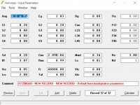
I believe I correctly entered the parameters for the XT25BG60 and a 1mm deep horn should have a minimal effect.
Is hornresp useless for the higher frequencies?
I believe I correctly entered the parameters for the XT25BG60 and a 1mm deep horn should have a minimal effect.
Attachments
Last edited:
I still get no HF output! What is going on?
The Tymphany XT25BG60-04 has a dual concentric diaphragm with a centre plug. Hornresp models the driver diaphragm as a rigid plane circular piston - not a good analog in this case. To further compound matters, you have calculated the acoustical power response, rather than the pressure response.
I didn't know I was talking to the man who created Hornresp. David, thank you sir for making this great tool for us to use. I am sorry to have used the word useless in my previous post. But I was just getting frustrated that the HF was drooping whatever parameters I entered. But it is very likely that I am the useless one here 😀
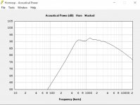
I followed your advice and learned how to model a ME horn. Does this sim look decent for a Synergy with Peerless XT25 and 4x Peerless TC9FD?
So now I have 3 Hornresp questions regarding Synergy sims:
1. Is the drooping HF expected and to be ignored?
2. I simmed with 4 mids series parallel. Does it sim them as one driver? I mean APT1 is one large port for 4 drivers so when building the horn I make 4 ports sized APT1 / 4. In my sim APT1 is 36 cm2 so i make 4x 9cm2 ports?
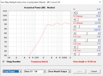
3. The SPL response I get in the ME wizard is different then when I use the calculate button. The wizard sims the horn is good from 400Hz up, calculated response says 600Hz and up....see attached images. Should I go with 400Hz?
I followed your advice and learned how to model a ME horn. Does this sim look decent for a Synergy with Peerless XT25 and 4x Peerless TC9FD?
So now I have 3 Hornresp questions regarding Synergy sims:
1. Is the drooping HF expected and to be ignored?
2. I simmed with 4 mids series parallel. Does it sim them as one driver? I mean APT1 is one large port for 4 drivers so when building the horn I make 4 ports sized APT1 / 4. In my sim APT1 is 36 cm2 so i make 4x 9cm2 ports?
3. The SPL response I get in the ME wizard is different then when I use the calculate button. The wizard sims the horn is good from 400Hz up, calculated response says 600Hz and up....see attached images. Should I go with 400Hz?
Attachments
you have calculated the acoustical power response, rather than the pressure response.
I don't understand what that sentence means.
"...acoustically cross the lower frequency driver(s) below the first cancellation notch--something that happens in the Unity horn, too, since the acoustic output of the lower frequency drivercannot produce sufficient SPL inside its first cancellation notch frequency band. "
Right, hence that's prior art done in then already marketed Unity horns. So how patented?
I think most people that understand the two patents (US6411718 Unity horn vs. US8284976 Synergy horn) would say that the second patent should not have issued, and that the patent examiner didn't fully understand the physics behind the two horns. You can see this in the "patent wrapper" where the responses to the claims 1-4 of the patent were reinstated after being disallowed by the examiner:
In all fairness, I think that the Synergy patent is there to create FUD in order to fend off the other big loudspeaker manufacturing companies with the wherewithal to undercut DSL's pricing from cutting into DSL's Synergy market share (which the US8284976 DSL patent has apparently done). I don't think that Danley himself is trying to keep DIYers from experimenting and improving the design....Also, as noted by the Examiner, Danley et al. [the Unity patent US6411718, now expired] does not teach use of at least one lower driver having upper frequency end lower than the frequency of a first cancellation notch...
On that note...all of my experience with the K-402-MEH shows that midrange drivers are not needed (as has been stated in this forum before) if the DIYer starts with a good 2" compression driver--including dual diaphragm types--thus bypassing the need for the "phase link" (B&O type) off-axis midranges found in the Unities and Synergies, since the DIYer doesn't need anywhere near the SPL output that commercial PA loudspeakers require--which is the driving requirement in their inclusion in the Unities and Synergies. The requirement for midrange drivers for home hi-fi use thus has been reduced in precedence to the level of their elimination in favor of a simpler two-way design--without detrimental effect on the phase response of the resulting DIY MEH.
YMMV.
Chris
By the way, I stated that the DIYer could start with a 2" compression driver. I would add that 1.4" and 1.5" throat compression drivers (with suitably designed horn throats) are also just as viable for the two-way application. The problem is actually the 1" compression drivers that most think is saving them money--but aren't at the end of the day.
Chris
Chris
Last edited:
About the number of midranges:
From the tweeter's point of view, the ports to the midrange do nothing good and some things bad. IMO, If adding more midranges doesn't help the SPL level that you'll ever use, you are only complicating things and degrading the tweeter's response and pattern. And the tweeter covers more octaves and in more audible regions than the midrange(s) will.
Bill makes a good point. While I was counseling headroom for excursion I meant precisely that, not SPL headroom. If I used 4 midranges, I would only make their ports large enough to support operation at a normal in-home listening level; not the pro-audio touring level it would likely be capable of with full size mid ports. Thus my horn would have about the same mid port hole area as Bill's but distributed across more, individually smaller holes.
Were I to do it again, I would likely only use 2 midranges but same principle applies; keep the holes as small as possible given intended listening level. (Check hole size by looking at particle velocity)
TC9 may not be your best choice = it requires a fairly large chamber volume, which can complicate your system design. Easiest solution is with a sealed back midrange which facilitates mounting woofers on the same horn.
The hole size issue is interesting. I should mention that Dr. Geddes apparently considers the mere need for any such holes proof that Synergy isn't the optimal solution. In the recent discussion here we've seen mention of Chris's MEH with 15" woofers on the sides of the huge but exemplary K-402 horn and P. Bateman's solution which is just about as small as one can get. Both good solutions or can be well integrated into the room; one requires a Texas sized room and quite large holes in the horn to support those large woofers playing as low as they do ,the other likely requires more in the way of room treatments.
I've gotten nothing to say about patents; its clear the system is broken given how many questionable patents are issued. I see Chris has his defense prepared🙂
...for all us DIYers...😀 (You might not recall that even DIY is technically disallowed for any patented invention--as a patent violation, which explains why most companies and other inventors doing benchmarking product upgrades always keep their prototypes concealed from public view.)... I see Chris has his defense prepared🙂
...Thus my horn would have about the same mid port hole area as Bill's but distributed across more, individually smaller holes...Were I to do it again, I would likely only use 2 midranges but same principle applies; keep the holes as small as possible given intended listening level. (Check hole size by looking at particle velocity)...The hole size issue is interesting...
Again from the Synergy patent (US8284976), with Danley himself speaking:
Clearly this is something I intend to test using a for-purpose K-402-sized MEH horn with much shorter ports than the ~3/4" length ones that I currently use (there are 19mm thickness MDF woofer mounting pads that are used on the opposite side of the prototype K-402 horn that's screwed to the side horn walls. These serve to seal the 15" woofer front chambers to the off-axis ports. Note that the current size of the woofer off-axis ports in the K-402-MEH are about the same size as those on the SH-50 in my possession....It is desirable to keep the acoustic output ports...relatively small (in cross-sectional area) to avoid acoustic discontinuities. It is been found that, with a minimum port length, the cross-sectional area or size of the port opening can be reduced significantly. In one example, ports in a prior art midrange section have a length of three quarters of an inch. By reducing the port lengths to 1/16 of an inch, the ports could be reduced in number from 8 to 4 and in size from ¾ of an inch to ⅝ of an inch.
I'm able to do without a center subwoofer using DSP EQ on these two 15" woofers and the resulting harmonic distortion levels are lower than the DIY TH subs on either side (i.e., Danley TH-SPUD designs with higher xmax woofers).
Chris
You can confirm Danley's comment re' port diameter vs length in HornResp simulation. IIRC In an "OD" simulation you can get back to the same pressure response if after halving the port area you then halve the port length.
Thus the recommendation for frustrumizing or tapering the port side walls - at attempt to decrease the effective port length. Perhaps less cut and try if you stiffen the side wall of your horn with an 1/8" aluminum plate.
Thus the recommendation for frustrumizing or tapering the port side walls - at attempt to decrease the effective port length. Perhaps less cut and try if you stiffen the side wall of your horn with an 1/8" aluminum plate.
I don't understand what that sentence means.
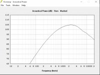
The power response of a speaker is the acoustic power that it radiates. The pressure response is the pressure it produces at some specific point in space, but the pressure response at a different point might be different. If you have a truly omnidirectional speaker, it has the same pressure response everywhere, and the power response and pressure response are the same. If you have a driver with a polar pattern that becomes increasingly narrow as frequency rises like a driver in a horn (very broadly speaking), then if you have flat pressure response on-axis, the power response will fall as frequency rises. Additionally, most drivers have a falling power response as frequency increases. So the on-axis pressure response is then a result of how the acoustic power produced is distributed in space. If you have a horn that distributes sound evenly, even if only across some limited angle, the power response of the system will fall.
So yes, it's normal that you're seeing a falling power response.
I am sorry to have used the word useless in my previous post.
Not a problem 🙂.
Does this sim look decent for a Synergy with Peerless XT25 and 4x Peerless TC9FD?
The response as shown looks fine to me. What happens above 2000 Hz? (Double-click on the "Frequency (hertz)" label beneath the chart to change the range).
Is the drooping HF expected and to be ignored?
The HF power response roll-off is to be expected. The pressure response takes directivity effects into account and is likely to hold up better at higher frequencies.
In my sim APT1 is 36 cm2 so i make 4x 9cm2 ports?
Correct.
The SPL response I get in the ME wizard is different then when I use the calculate button.
When you click the Calculate button on the Nd record, only the system specified by the Nd record itself is simulated - the ME1 record is not taken into account. If you check the schematic diagram you will notice that the ME1 drivers are not present.
The HF power response roll-off is to be expected. The pressure response takes directivity effects into account and is likely to hold up better at higher frequencies.
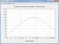
To illustrate, the grey trace in the attached chart shows the acoustical power response of the Hornresp default driver in an infinite baffle. The black trace shows the on-axis pressure response for the same system.
Attachments
Thanks David and John. I couldn't figure all this out on my own. I am getting the hang of modeling ME horns in Hornresp. Also reading the original patents and trying to completely understand them helps me a lot. I am waiting for my drivers from Digikey so I can make a test horn and play around with the model and port locations, sizes & shapes. I am sure more questions will arise out of that.
- Home
- Loudspeakers
- Multi-Way
- Suitable midrange cone, for bandpass mid in Unity horn