Hi,
Thanks for that.
What do you mean by indirect? I was going just to connect an SMPS to a 7806 and apply that to the heaters.
Thanks for that.
What do you mean by indirect? I was going just to connect an SMPS to a 7806 and apply that to the heaters.
Both tubes don't feature a filamentary (= directly heated) cathode, but a coated sleeve instead with the heater inside and isolated.
Best regards!
Best regards!
Kay is saying that the heaters are not connected to the cathode, some tubes use the heater as a cathode (directly heated). The heaters are electrically isolated and you can do what you want as long as you do not exceed the heater to cathode voltage spec.
Hello, just for additional information, some output transformers are available at mouser too : Access to this page has been denied.
It's not cheap but it should work great 😉
Not exactly matching subminiature amp requirements but maybe for your second design 😉
It's not cheap but it should work great 😉
Not exactly matching subminiature amp requirements but maybe for your second design 😉
Attachments
I'm using the Hammond 1750E for 2 - 6P30B's in push-pull @ 300V. I figured out I'm going to have to put a 16 ohm speaker on the 8 ohm secondary to reflect 17,000 ohms on the primary to keep everything happy. (Apparently, 6P30B has a load resistance approx. 8500 ohms @ 300V.)
Set me back $55 so I can see why some guys like to use line voltage tranformers you can pick up for $10 or so. I just have too much time invested in this to try something that might not have good frequency response.
Set me back $55 so I can see why some guys like to use line voltage tranformers you can pick up for $10 or so. I just have too much time invested in this to try something that might not have good frequency response.
Hi,
I have a doubt on the specs of the transformer.
It is not obvious to me, the correspondence between the left and right columns.
Do the primary impedances correspond to a load of 4, 8 or 16 ohms?
Cheers
Pedro

I have a doubt on the specs of the transformer.
It is not obvious to me, the correspondence between the left and right columns.
Do the primary impedances correspond to a load of 4, 8 or 16 ohms?
Cheers
Pedro
Last edited:
The ratio of transformer is: n1:n2 = 1000/4 = 2000/8 = 4000/16 = 250 -> same for the 3 "cases" of course.
It means that the output impedance (where you plug the speaker) is 4R (R is ohm) if the input impedance (tube side) is 1k, 8R if impedance on the tube side is 2k, ... For power it is the same thing:
1. P=10W @ 4R
2. P=5W @ 8R
3. P=2.5W @ 16R
For example, if your impedance on the tube side is 1500 ohms then output impedance will 6 ohms.
Last edited:
Hi,
Thanks for the reply. My doubt it was regarding that correspondence, from the column on the left to the right. If they really wanted to say 1k to 4; 2k to 8; etc , shouldn't the others be there (32 and 64)?
I believe your calculations are not correct, since the ratio between impedances, doesn't equal the ratio of number of turns, but the square of the number of turns.
If P=V^2/R, where V=N
we can say that:
Pp=Ps -> Vp^2/Rp=Vs^2/Rs.
As Vp/Vs=Np/Ns
Np^2/Ns^2=Rp/Rs -> Np/Ns = squareRoot(Rp/Rs)= squareRoot(250)=15.8
Best regards,
Pedro
just found this: Guide to Transformers -- Audio Transformers
Didn't read it in details ... maybe later.
Didn't read it in details ... maybe later.
yes, ratio n1/n2 is for voltage & current only.
n1/n2=V1/V2=I2/I1 -> P1=P2
Sorry for mistake 😉
You don't have to apologise. You are helping me.
I have just taken a look at the link and it seems quite nice.
I will read it today.
Thanks a lot.
Cheers
Pedro
Last edited:
Hi,
I don't know if you agree with this but, to me, the list on the left only tell us correspondence between power and resistance, whereas the second the output impedances available to be used. BAsically 2 columns that tell you which inputs and outputs are available.
So, to me, it's not 1k to 4ohm, 2k to 8 ohm, etc. All of them could be used in any combination, 1k with 4ohms, 2k with 4 ohms, 1k with 8 ohms, etc.
If I am correct, I don't know for which value of secondary output, the primary resistance was calculated.
Any thoughts on this?
Cheers,
Pedro
You maybe right because I supposed that the ratio was constant. However, it is maybe not the case. If you have access to intermediate transformer parts (through some of wires), you can have multiple ratio and so have all possible combination. I think we should see the wiring diagram but in the picture, only 2 wires in one side and 3 wires on the other side. No wiring diagram on Hammond website.
Hi, there are some better datasheets out there (check mouser, every part has a datasheet). I would guess it is the same as other transformers out there. (725, 300, 400, 600, 900 turns at the primary and 48,18, 30 turns in the secondary)
The primary impedances are for all the secondary impedances. You can get 16k using 4 ohms on the 4 ohms tap, 8 ohms on the 8 ohms tap and 16 ohms on the 16 ohms tap. Because the ratio is kept constant if you use the right tap.
If you mismatch speaker impedance and tap impedance, on the other hand, you can get 64k with a 16 ohms speaker on the 4 ohms tap.
Hi Thomas,
Thanks for your answer. This transformer looks similar in terms of spec as the one you used on the battery amp that you have on instructables. And for that one, the primary turns are different.
Do you think the two transformers are equivalent?
Cheers
Pedro
Thanks for your answer. This transformer looks similar in terms of spec as the one you used on the battery amp that you have on instructables. And for that one, the primary turns are different.
Do you think the two transformers are equivalent?
Cheers
Pedro
Exactly, I think they might be similar.
I could not find much information on the monacor website, but maybe there is an older datasheet out there.
I could not find much information on the monacor website, but maybe there is an older datasheet out there.
Hi
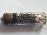
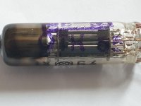
Can someone please help me finding the pinout for this tube?
I was expecting to see a mark of some kind, but I can't see one.
Please check the pictures attached.
Thanks,
Pedro
Can someone please help me finding the pinout for this tube?
I was expecting to see a mark of some kind, but I can't see one.
Please check the pictures attached.
Thanks,
Pedro
Attachments
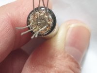
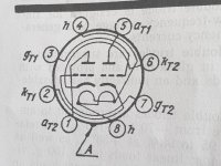
Are the triodes dissimilar? If they aren't, identifying the pinout isn't that difficult: Both heater wires are arranged in opposition, and the electrode wire sequence exactly repeats.
Best regards!
Best regards!
- Home
- Live Sound
- Instruments and Amps
- Subminiature tube/valve guitar amplifier