Oh, so you've been in OB camp. Do a quick search and found your name among threads of current drive, T-bass.. etc. Do you use them?
If you had experienced T-bass or high impedance drive, then you should try slot-loaded. It brings quite a significant improvement in punch and weight. Subjective, yes, but I'm quite sure it's there.
Horn, very charming, I admit. And the iron law applies here -- bigger is better. See this:
http://www.diyaudio.com/forums/multi-way/125349-3way-horn.html
It's about 150 x 120 x 80 cm overall, I guess you can handle the size. If you're interested, I'll find you the folding.
I had 5 x 18" full lenght U-frame line arrays (over 1sqm of total cone area🙂), 10 x 8" near full lenght midbass "L-baffle" linearrays and >2m tall electrostats at some point. They definitely slammed good and I will setup them later when I get bigger listening room. I like having 2-3 possible setups. Dipoles have their ups and downs just like anything.
I have been using current drive for compression driver, 12" full rangers and super tweeter, but not for specialized woofers. I have been going from active to passive setup from time to time but the current drive has only been done in passive setups. Have not touched DSP in over a year now, but next (this) project I will be doing active for the obvious reasons. Never tried the T-bass.
The horn speaker you linked speaker looked very nice, but the bass section (FLH?) was too big. I honestly think that 100cm x 100cm would the maximum comfortable footprint of one channel, but height can be anything that fits the room (keeping in mind that other horns will be stacked upon each other, TH being at the bottom, MB horn over it etc...). Also the extension to 20Hz is a requirement, I'm not going to make compromises in that regard.
The PPTH would be interesting route (instead of PPSL) if a smooth and wide enough response can be realized, given the size limits, with a 2x18" PPTH.
Last edited:
Legis,
So is the design constraint 1m x 1m footprint and 20Hz extension? I will see if I can squeeze a dual dipole TH into this as you say height is not constrained (for reasonable heights of say 8 ft ceiling). It will be push-pull but the push and pull will be two separate drivers in two separate horns. What is the high freq XO point these need to be flat to?
X
Legis,
So is the design constraint 1m x 1m footprint and 20Hz extension? I will see if I can squeeze a dual dipole TH into this as you say height is not constrained (for reasonable heights of say 8 ft ceiling). It will be push-pull but the push and pull will be two separate drivers in two separate horns. What is the high freq XO point these need to be flat to?
X
No dipole TH's, just regular PPTH. What are you trying to achieve with dipolic operation? Dipole is not some magic, at least where i live 🙂, no offence to anyone.
FYI, I have also been thinking that the MB horn will possibly have a back chamber. But I decide that when I can compare how much the rear radiation screws up resolution and clarity in my untreated room. If it does not do much, I like to keep the drivers open for the looks and for the smaller weight.
Legis,
OK, just PPTH in monopole then. I did however verify that you can get true dipole behavior even at very low frequencies which are normally omni and non-directional. Here is a dipole TH using the TH-18 design (http://www.diyaudio.com/forums/subwoofers/190635-th-18-flat-35hz-xoc1s-design.html). It is 0.72 m deep x 0.53 m wide so when stacked back to back the depth is 1.44 m deep - too big. It could easily be folded differently to be taller and maintain the 1 meter depth. I know you do not require dipole anymore for the bass but I was curious so ran the sim anyway - it was an easy copy and paste of a single horn into two systems placed with mouths 180 deg apart and fired out of phase.
Here is the response at 2 m with cone driven to xmax for a single horn (mono-pole operation, no LPF but with 30 Hz HPF:

Here is the corresponding response for a di-pole TH, note the characteristic -6dB/oct fall-off associated with dipole radiation. This of course can be compensated in EQ, you certainly have the headroom given the max SPL this thing puts out:

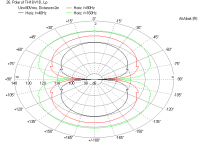
Here is the polar response for the above dipole TH over 360 deg at 2 m away. True dipole radiation pattern even for 40 Hz!

Ok, back to designing a PPTH that reaches 20 Hz now...
OK, just PPTH in monopole then. I did however verify that you can get true dipole behavior even at very low frequencies which are normally omni and non-directional. Here is a dipole TH using the TH-18 design (http://www.diyaudio.com/forums/subwoofers/190635-th-18-flat-35hz-xoc1s-design.html). It is 0.72 m deep x 0.53 m wide so when stacked back to back the depth is 1.44 m deep - too big. It could easily be folded differently to be taller and maintain the 1 meter depth. I know you do not require dipole anymore for the bass but I was curious so ran the sim anyway - it was an easy copy and paste of a single horn into two systems placed with mouths 180 deg apart and fired out of phase.
Here is the response at 2 m with cone driven to xmax for a single horn (mono-pole operation, no LPF but with 30 Hz HPF:
Here is the corresponding response for a di-pole TH, note the characteristic -6dB/oct fall-off associated with dipole radiation. This of course can be compensated in EQ, you certainly have the headroom given the max SPL this thing puts out:
Here is the polar response for the above dipole TH over 360 deg at 2 m away. True dipole radiation pattern even for 40 Hz!
Ok, back to designing a PPTH that reaches 20 Hz now...
Attachments
Just to clarify and to keep the big picture in mind, right I'm trying to design the bottom most box in something-like-this "speaker":
Midbass horn is quite ready-ish as a design, the plan for the low end (10...20 - 100Hz) is still completely open.
When I said that the height can be anything, I ment that the speaker as a whole can be almost as tall as the room. I can always point the midrange horn downwards if the lower two bass horns get taller.
That being said, I would still prefer that the bottom most box (PPTH, PPTL or whatever) would be 60cm tall. It makes things easier, less weight etc. The mouth of the midbass horn will be 50-60cm tall also. That leaves the height of the midrange horn's center point (with 60cm dia. horn in this example) to somewhere around 160-170cm and the total height of the speaker would be approx. 190-200cm. That is all the speaker's feet/spikes and possible platforms etc. included. I'm thinking to use some brass or aluminum spikes/feet and wooden pucks and/or platforms under each section to decouple them from each other. They might increase the whole height by 10-20cm total.
Sorry for keeping you guys confused 😀. You have been the greatest help this far, as you have seen my visions have changed rapidly.
An externally hosted image should be here but it was not working when we last tested it.
Midbass horn is quite ready-ish as a design, the plan for the low end (10...20 - 100Hz) is still completely open.
When I said that the height can be anything, I ment that the speaker as a whole can be almost as tall as the room. I can always point the midrange horn downwards if the lower two bass horns get taller.
That being said, I would still prefer that the bottom most box (PPTH, PPTL or whatever) would be 60cm tall. It makes things easier, less weight etc. The mouth of the midbass horn will be 50-60cm tall also. That leaves the height of the midrange horn's center point (with 60cm dia. horn in this example) to somewhere around 160-170cm and the total height of the speaker would be approx. 190-200cm. That is all the speaker's feet/spikes and possible platforms etc. included. I'm thinking to use some brass or aluminum spikes/feet and wooden pucks and/or platforms under each section to decouple them from each other. They might increase the whole height by 10-20cm total.
Sorry for keeping you guys confused 😀. You have been the greatest help this far, as you have seen my visions have changed rapidly.
Last edited:
Legis,
In order for a TH to reach 20Hz it has to be quite long (volume will be big). From my experience in designing a TH, I am not sure if you can get one to reach 20 Hz given the 18 in driver size. You may be better off with dual push pull 12 in drivers that can get a smaller box with a longer path. You said your PPTH design in the above sketch reaches 20 Hz in a HR sim? What is the unfolded length on that horn? I am having a hard time seeing how to fold 14 feet of path length into a box the size you draw.
In order for a TH to reach 20Hz it has to be quite long (volume will be big). From my experience in designing a TH, I am not sure if you can get one to reach 20 Hz given the 18 in driver size. You may be better off with dual push pull 12 in drivers that can get a smaller box with a longer path. You said your PPTH design in the above sketch reaches 20 Hz in a HR sim? What is the unfolded length on that horn? I am having a hard time seeing how to fold 14 feet of path length into a box the size you draw.
Legis,
In order for a TH to reach 20Hz it has to be quite long (volume will be big). From my experience in designing a TH, I am not sure if you can get one to reach 20 Hz given the 18 in driver size. You may be better off with dual push pull 12 in drivers that can get a smaller box with a longer path. You said your PPTH design in the above sketch reaches 20 Hz in a HR sim? What is the unfolded length on that horn? I am having a hard time seeing how to fold 14 feet of path length into a box the size you draw.
It seems that the narrower/tapered parts in the "horn" lower the loading point so the lenght can be little shorter. Also the biggish back "chamber" (L12) did lower the loading. I'm very unexperinced with Hornresp though, I see what I can scrape off after I have hit the gym.
Btw, is the acoustic path lenght measured by shortest path possible inside the horn from point A to point B (going alongside the walls in turns) or at the center of the horn even at 90 degree turns? If this makes any sense.
The path I use to model a horn is the middle of the channel. If you look at the example of the TH-18, this is how it was modeled by X0C1:

As you can see, turns are handled by breaking down into wedges and the CSA first expands then contracts. This is how you do it with a comprehensive Akabak model because it can handle all those nodes. In Hornresp, you have 4 segments and you ignore all the turns. Just use the pathlength from the middle of the channel for HR. It will come out very close to the full model with all turns accounted for.
Hope this helps.
First try, not that good result overall. What dimension causes the null at 95Hz?
Not as much natural low end response as I'd hoped for, but max SPL @20Hz is quite ok. Loading at 40-45Hz is quite horrible.
The measures are not very accurate, I just estimated them. The woofers are also little too shallow maybe in the pictures.
(Max SPL at 19mm/500w)
Not as much natural low end response as I'd hoped for, but max SPL @20Hz is quite ok. Loading at 40-45Hz is quite horrible.
The measures are not very accurate, I just estimated them. The woofers are also little too shallow maybe in the pictures.
An externally hosted image should be here but it was not working when we last tested it.
An externally hosted image should be here but it was not working when we last tested it.
(Max SPL at 19mm/500w)
An externally hosted image should be here but it was not working when we last tested it.
An externally hosted image should be here but it was not working when we last tested it.
20 Hz PP Tapped Horn with dual 12 in drivers
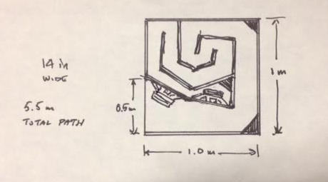
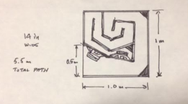
I came up with a rough design for a push-pull TH using two 12 in drivers that fits in a 1.0 m x 1.0 m footprint that is 0.40 m tall. The total folded pathlength ended up at 5.5 meters which gets you down to 20 Hz. I ended up using some rather budget drivers but their specs seem to fit the bill (low fs, lowish Qts, moderate effficiency, long stroke). These are Infinity 1260W car audio subs (4 ohms) connected in series for 8 ohms. The nice thing is that these drivers are $62 (shipping included) from Amazon in the US 😀.
Here is the conceptual sketch which led to a simplified 7 segment horn model:
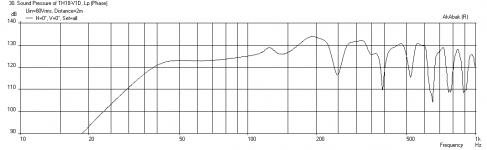
Here is simulation at 50 volts with an xmax of 13 mm (above 20 Hz), below that I am going higher than xmax but below xdamage. A 17 Hz -24dB/oct HPF and 95 Hz -48dB/oct LPF were applied:
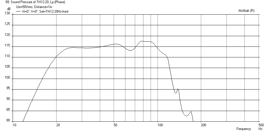
As you can see, the bass extension goes to 21 Hz (-3dB) and is fairly flat up to 100 Hz where you are XO to the mid bass horn. This design has not been optimized at all so the efficiency is not very good for a tapped horn, but I wanted to see that a 5.5 m long path could be squeezed into a 1m square footprint with horn lying on its side.
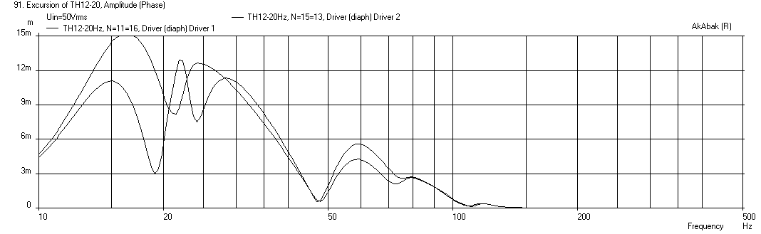
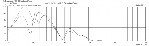
Here is cone displacement, which you can see is not symmetric given the fact that the drivers are located at different points on the horn - and I think this actually helps to smooth the output.
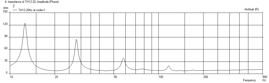
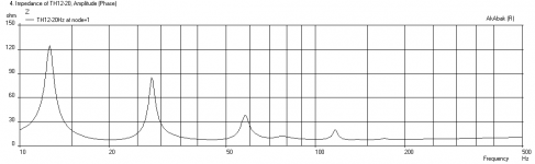
Here is the electrical impedance:
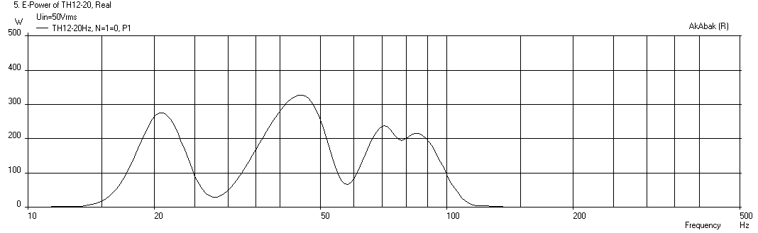
Here is the electrical power to reach xmax - need a 350 watt amp:
I came up with a rough design for a push-pull TH using two 12 in drivers that fits in a 1.0 m x 1.0 m footprint that is 0.40 m tall. The total folded pathlength ended up at 5.5 meters which gets you down to 20 Hz. I ended up using some rather budget drivers but their specs seem to fit the bill (low fs, lowish Qts, moderate effficiency, long stroke). These are Infinity 1260W car audio subs (4 ohms) connected in series for 8 ohms. The nice thing is that these drivers are $62 (shipping included) from Amazon in the US 😀.
Here is the conceptual sketch which led to a simplified 7 segment horn model:
Here is simulation at 50 volts with an xmax of 13 mm (above 20 Hz), below that I am going higher than xmax but below xdamage. A 17 Hz -24dB/oct HPF and 95 Hz -48dB/oct LPF were applied:
As you can see, the bass extension goes to 21 Hz (-3dB) and is fairly flat up to 100 Hz where you are XO to the mid bass horn. This design has not been optimized at all so the efficiency is not very good for a tapped horn, but I wanted to see that a 5.5 m long path could be squeezed into a 1m square footprint with horn lying on its side.
Here is cone displacement, which you can see is not symmetric given the fact that the drivers are located at different points on the horn - and I think this actually helps to smooth the output.
Here is the electrical impedance:
Here is the electrical power to reach xmax - need a 350 watt amp:
Attachments


Last edited:
In 1m² floor space the Othorn would be a good pick, Ricci has refolded this recently and to my eye it looks like a decent choice.
In 1m² floor space the Othorn would be a good pick, Ricci has refolded this recently and to my eye it looks like a decent choice.
I like the Othorn too but I think it is a 30 Hz design and Legis said he wanted a true 20 Hz TH. Is the re folded Othorn a 20 Hz capable design?
Here is the predicted performance of the original Othorn:
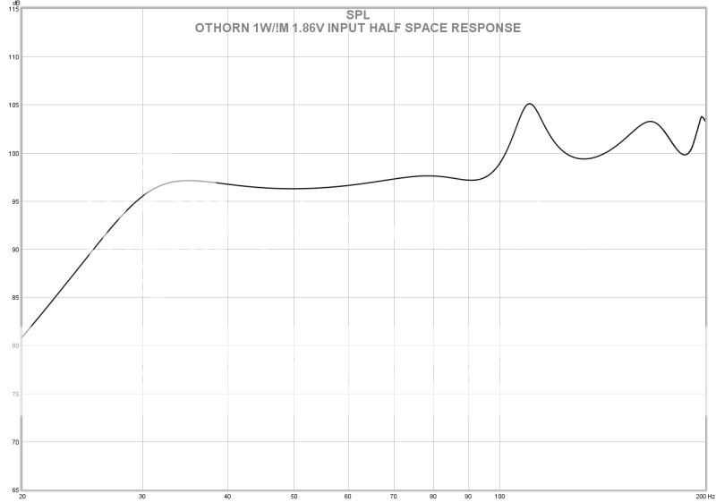
True. The Othorn is not going to do 20Hz with massive authority, but it's what it does do that makes it so good. It will go up high enough to mate to the proposed MB horns, where a 20Hz TH cannot due to it's larger & lower group delay honk. The Gjallarhorn is a good example, it goes lower than 20Hz and has an annoying honk in the 60Hz decade, however if your mains are 40Hz capable this is not much of a problem. One is good for LFE and the other is good for everything else. The Othorn is also 130dB capable, unlike most others. I've heard them and if I were constrained to that form factor I would have already built some, that's why I recommended it.
Hi X,
Thanks for the kind words. In fact, I haven't had time to tune that big system thoroughly enough. Just did the overall design and initial setup. There's surely protential to be better, especially in the overall integration.
Later I've heard there's some concerns and inconvenience about the full (digital) active arrangement, so the user got someone else to modify it into passive-xovered. In which I haven't joined, so it's getting out of my hands. It's really a shame I can't put more time on it.
And yes, it's a studio, in a university managed by a friend.
------------
Legis,
Wow, your OB system is awesome. And you should try current (high impedance) drive on the LF section. I feel it's significantly better than other type of EQ for OB bass. (I guess the overall gain structure plays an important role here.)
And, you might have already seen the trend along various sims here and there. It's really hard (or impossible) to get optimal overall performance with the restriction of size. Bass horn is more so than other types when facing the iron law. When you strive to get 20Hz, many other aspects are sacrificed inevitably, and hard.
Look commercial products, the best horns out there are mostly designed for 4-stack, and even then they don't get down to 20Hz flat. Mostly 27-28 Hz at best. For a single horn, it's surely weaker. It's the physics we can't fight.
Although it's not necessary to get highest possible efficiency (and SPL) in domestic use, it's still hard to accept inferior overall performance, including ripple, impulse/phase response... etc. And there's the consideration of the whole system.
This leads to a tough question for you: would it be a good choice to add a compromised bass horn to this otherwise no holds barred system ?
.......
Say, I've tried reverse-engineering one of the highly regarded BLH for Lowther - Acousta, and I saw things not pretty, TBH. When it comes down to commercial products, compromise is the first word. I'd rather not stepping into that route in DIY.
I was asked to design BLH by some friends in love with Lowther. Almost no exception, when everything looks decent to excellent in the sims, I came up with overall size of a fridge. As you can imagine, friends were all crying for a smaller size. Eventually I can only accept a slightly smaller fridge. "Or, please just give up horn if size is a major concern" I told them. No free lunch, sad but true.
True. The Othorn is not going to do 20Hz with massive authority, but it's what it does do that makes it so good. It will go up high enough to mate to the proposed MB horns, where a 20Hz TH cannot due to it's larger & lower group delay honk. The Gjallarhorn is a good example, it goes lower than 20Hz and has an annoying honk in the 60Hz decade, however if your mains are 40Hz capable this is not much of a problem. One is good for LFE and the other is good for everything else. The Othorn is also 130dB capable, unlike most others. I've heard them and if I were constrained to that form factor I would have already built some, that's why I recommended it.
The PPTH that I just came up with doesn't have honk either (if honk is that first big peak before the dip) within the 20hz to 100hz bandwidth - although I am using a trick not shown in the diagram to suppress it passively within the enclosure. It just doesn't get as loud. Maybe if I got rid of the dual 12 in PP drivers and went with a single 21 in PA driver it can get loud.
Last edited:
Say, I've tried reverse-engineering one of the highly regarded BLH for Lowther - Acousta, and I saw things not pretty, TBH. When it comes down to commercial products, compromise is the first word. I'd rather not stepping into that route in DIY.
I have modeled the Zen Acousta horn that uses a Lowther - are we talking about the same curved wooden horn that hangs on rope from a frame? It was not the smoothest response or the deepest bass given how big it was.
21 inch 20 Hz TH
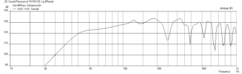
I had to try it - I took the same exact design for the 12 in PPTH above and increased the width to 24 in to hold a 21 inch B&C 21SW152-4 driver. This monster of a driver has a Nd motor with a Bl of 32.5 and an xmax of 15 mm. Anyhow it worked out beautifully. Same 1 meter square footprint, it is just now is 25.5 in tall (0.65 m). Single driver rather than dual PP. Here is what you can get from it at 67 volts drive (about 1 kW) to hit xmax:
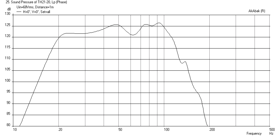
I had to try it - I took the same exact design for the 12 in PPTH above and increased the width to 24 in to hold a 21 inch B&C 21SW152-4 driver. This monster of a driver has a Nd motor with a Bl of 32.5 and an xmax of 15 mm. Anyhow it worked out beautifully. Same 1 meter square footprint, it is just now is 25.5 in tall (0.65 m). Single driver rather than dual PP. Here is what you can get from it at 67 volts drive (about 1 kW) to hit xmax:
Attachments

Last edited:
No 'Zen' in the name, just 'Acousta', or the complete name is Acousta 115, the classic one:
www.audiofaidate.org • View topic - Lowther Acousta 115
-----
About the horn with 21", under 40Hz, less than 125dB @ 1kW. (And that's about 95dB @ 1W, right?) Hmmm... I guess the driver would give similar performance in a bandpass or vented box.
I'm afraid it's not worth the effort to build a horn, then. 🙁
Or, look at it in another viewpoint. Try making a sim with the same driver and an optimal horn profile, compare the results. It'll be stunning.
Last edited:
The TH sounds much cleaner though - the group delay and transient response is better than reflex. An optimized TH with this driver should be able to achieve higher efficiency. I just have not had time to optimize it - this is literally the first sim that came from the dimensions on my sketch. I never even touched HR which has sliders to optimize on the fly.
I had to try it - I took the same exact design for the 12 in PPTH above and increased the width to 24 in to hold a 21 inch B&C 21SW152-4 driver. This monster of a driver has a Nd motor with a Bl of 32.5 and an xmax of 15 mm. Anyhow it worked out beautifully. Same 1 meter square footprint, it is just now is 25.5 in tall (0.65 m). Single driver rather than dual PP. Here is what you can get from it at 67 volts drive (about 1 kW) to hit x-max.
How would the BMS 18N862 work in this design?
Frode
- Status
- Not open for further replies.
- Home
- Loudspeakers
- Subwoofers
- Study of a Dipole/Cardioid Bass Horn