Thanks Steveu, yes a current limiting resistor is need, i will post a new diagram in a new Power supply thread.
how do you calculate the value ?
how do you calculate the value ?
There are more issues but starting with the current limiting resistors:Thanks Steveu, yes a current limiting resistor is need, i will post a new diagram in a new Power supply thread.
how do you calculate the value ?
1. The current sense base resistor just has to limit the base current to something the transistor base can survive for a very short period. A 100 Ohm resistor is commonly used here but it could be as large as 1K. A 91V transient on a 100 Ohm resistor is 0.91 Amps peak which is too high for a small transistor but it only lasts for a ~millisecond.
2. The collector current limit resistor is similar. The 100uF cap can have 65x1.4=91V max and we need to limit the collector current in a similar way to the base current, but too much will mess with the 2EF bias. 10% of the 3.3K is 330, and or you could use 2k7 instead of 3k3 and a 680 after the cap.
Then there is the output voltage divider and the Zenner. With a 20V Zenner, the 10K+2k2+2k2 divider has a range of 20.65 x 14.4/2.2 = 135 to
20.65 x 14.4/4.4 = 67.5. Given that the raw voltage is about 91V, much of that divider range is useless. I would change the 10K resistors to 5.6K so that the adjustment range is 20.65 x (5.6+4.4)/2.2= 93V (91) to 20.65 x (5.6+4.4)/4.4= 47V. And watch out for the dissipation of those resistors: 91/14k4=6.3mA = 0.575 Watts. And 91/(5.6k+2k2+2k2)=9.1mA=0.83Watts. Maybe using 15V Zeners would be a better idea so that 15.65 x 14.4/2.2=102 (91) and 15.65x14.4/4.4=51.
Last edited:
PS:
This assumes you are happy with a protection current of 2x 0.65V/0.22 Ohms = 5.9 Amps. You can adjust the 0.22 emitter resistors or make the base current limit resistor into a divider to make the current limit higher. Or you can add a resistor to the raw supply to make the protection into VI protection. Depending on your heat sink, 5.9 Amps might overheat in a hurry, but it is suitable for short term overloads.
This assumes you are happy with a protection current of 2x 0.65V/0.22 Ohms = 5.9 Amps. You can adjust the 0.22 emitter resistors or make the base current limit resistor into a divider to make the current limit higher. Or you can add a resistor to the raw supply to make the protection into VI protection. Depending on your heat sink, 5.9 Amps might overheat in a hurry, but it is suitable for short term overloads.
hello, who assembled this amplifier, tell us the nuances about assembly and tuningВершина SR100F
Apex SR100F... не тестировался.
Можно ли заменить 2ск117 на 2ск170, 2ск246?
 Please post in English. Rules.
Can I replace 2sk117 with 2sk170, 2sk246?
Hello all,
could you confirm me that the SR150 is good for a new project ?
Is it the last revision of the shematic attached to the post : https://www.diyaudio.com/community/threads/studio-reference-amplifier.173462/post-4853925
Thx a lot
could you confirm me that the SR150 is good for a new project ?
Is it the last revision of the shematic attached to the post : https://www.diyaudio.com/community/threads/studio-reference-amplifier.173462/post-4853925
Thx a lot
Which one is correct?Turn on/off mute with FET. Also can be add thermal protect with muting input over 90deg on heatsink.
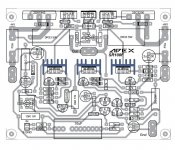
I am showing 2 pictures .
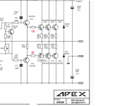
1st picture is Sir mile say q2 to q9 base to collector
2nd picture is by mistake q2 to q9 collector to collector.
When I attach pf q2 to q9 b to c sound is so so .its like sound little compress
When I attach pf q2 to q9 c to c sound is so beautiful low is very good .HIGH IS ALSO FINE
I AM ASKING TO MY professional . IS THIS SAFE OR NOT . GUIDE ME THANKS
of course it will, because you are introducing additional Miller correction capacitance, which increases the dynamic capacitance value in the load of the voltage amplifier driver, by the amount of amplification of the cascades Q1Q3Q6Q8 for one half-wave andWhen I attach pf q2 to q9 b to c sound is so so .its like sound little compress
Q4Q5Q7Q10Q9 for another half wave, which degrades work the output stage in push-pull mode.
When I attach pf q2 to q9 c to c sound is so beautiful low is very good .HIGH IS ALSO FINE
I AM ASKING TO MY professional . IS THIS SAFE OR NOT . GUIDE ME THANKS
What is the reason that you poke a capacitor anywhere?
Last edited:
Hello sir thanks for reply first.and I am not connected capacitor in any where . With Do you Respect. It's was my mistake. I am new diyyer. And I do practically. I will show my youtube video link plz checkWhat is the reason that you poke a capacitor anywhere?
ok, but the fact is that in such an inclusion, you introduce positive feedback to super-HF, if for some reason the switching of the output transistors slows down, you may get excitation ....I am use q2 to q9 collector to collector 18pf
You have not answered the question about the reasons for the introduction of unnecessary additional correction by you ....
in the circuit I see only the absence of base resistors damping the input capacitance of the output transistors ...
Attachments
I don't quite understand what should I check?plz check
when using the Q2 Q9 connection, the influence frequency is in the unity gain frequency range, and this is about 2-10 Megahertz, I don’t hear such frequencies, can someone else from the guru hear such frequencies? I definitely don't....
When using Miller's correction, to get a unity gain frequency in the range of 4-6 megahertz, the rolloff must start from the frequencies of the audio range, i.e. from the frequency of the pole, and this is sometimes even lower than 1 kHz, so Miller's correction is audible to the human ear ...
Yes, check if it is oscillating if you can, and look for DC offset at the output.
Ultimately if the circuit is stable and does not malfunction, then there is no reason it is "wrong" for the purposes of audio. But it could be difficult to confirm whether this is the case and changing the speaker or speaker cable could set it off even if it is stable with the initial test bench.
EDIT: Also check if the output stage bias is normal, if the VAS oscillates the bias can go high or low.
By the way, there is no Bushe coil at the output of the amplifier, which protects the negative coupling removal circuit from the capacitive nature of the load of the speaker system. This may affect the stability of the amplifier.
And like any homemade devices, it is very important to properly ground center wire inside the amplifier case.
And like any homemade devices, it is very important to properly ground center wire inside the amplifier case.
- Home
- Amplifiers
- Solid State
- Studio Reference Amplifier