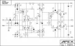
The 2SK170 and 2SJ74 are 0.95nV/√Hz voltage noise, but they are placed _after_ a 100k volume pot... Intentional? Even the two 220 ohm resistors in each signal path create 2.7nV/√Hz in themselves, making the choice of such ultra-low noise FETs fairly superfluous.
The volume pot worst-case will add 20nV/√Hz or so.
The volume pot worst-case will add 20nV/√Hz or so.
Hi Apex, i am building this regulated PSU for testing different amps.Regulated PSU is for single channel, two for stereo (dual mono). Stabil rail voltage is important for Reference Amplifier, it's simple PSU can be use for any DIY amplifier, and you can adjust different rail voltage for testing different amps.
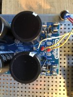
i have 43.5 Vdc output with 32Vac transformer. when i adjust the 2k2 Multiturn Trimmer Potentiometer, the output doesn't change (43Vdc). I have no load.
In the same time the voltage across the 20V Zener have variation from 6V to 12V. Your thought please.
Attachments
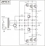


Looking at the schematic, this circuit is for use with a 2x65VC transformer, and the minimum regulated output voltage is about 67 Volts. (20.65*14.4/4.4) If you want a lower voltage power supply, you should use lower voltage Zeners and/or change the feedback resistors. I would suggest a Zener just less than the lowest useful output voltage; change the 10k resistors to a small value like 100 Ohms, and change the 2.2k Resistors Rx so that 43/Vz= (2.2k(pot)+Rx)/Rx. For a 10V Zenner, that would be 2.2k(pot)*10.65/(43-10)=~710 Ohms. It would be better if the pots were 10K and not 2.2k since 43V^2/2.9K = 638mW, too much power for a small pot.Hi Apex, i am building this regulated PSU for testing different amps.
i have 43.5 Vdc output with 32Vac transformer. when i adjust the 2k2 Multiturn Trimmer Potentiometer, the output doesn't change (43Vdc). I have no load.
In the same time the voltage across the 20V Zener have variation from 6V to 12V. Your thought please.
This circuit is not well suited for a general-purpose variable supply. You should use a circuit that uses a single pot for both positive and negative output. I can throw one up in spice and repost it in a few minutes.
Appreciated your suggestion Steveu, i would like to keep this new Board.Looking at the schematic, this circuit is for use with a 2x65VC transformer, and the minimum regulated output voltage is about 67 Volts. (20.65*14.4/4.4) If you want a lower voltage power supply, you should use lower voltage Zeners and/or change the feedback resistors.
Could you explain your formula to come to 67V?
i knew and figured out that for this secondary voltage (35v) that will be to low for the 20v Zener, but actually i have just this tranfo for my test and i may be have to change the Zener to 12V or 6.5V just to test the PSU.
This circuit work perfectly, i built it some time ago for 65V secondary.
I am not familiar with spice, by any chance do you have this Apex schematic in spice? I would like to try different value to adapt it to my needs
The minimum regulation voltage is when the pot slider is connected to the 10K so that the output voltage times (2.2K+2.2k)/(2.2k+2.2K+10K) is equal to the 20V Zener Voltage plus the transistor Vbe (0.65V). So the minimum regulated voltage is 20.65 *14.4/4.4 = 67.58V. The 10K limits the range but it should not be reduced to zero because that would expose the Zener and transistor to high current transients when the pot is set to min voltage. There is a small possibility of stability problems if the divider ratio is too small but unlikely. If you are going to learn spice, entering this circuit would be a good learning exercise. I think the transistors used are in Bob Cordel's library. Just changing the Zener to a 10V would work well, but it would not improve the voltage range.
I was thinking that my alternate circuit may need another stage in order to deliver high currents; easy to do. I didn't simulate that and I'm not sure what currents are required.
I was thinking that my alternate circuit may need another stage in order to deliver high currents; easy to do. I didn't simulate that and I'm not sure what currents are required.
hello, I collect sr100, the supply voltage will be + -35 or + -40v. how to calculate the resistors in the +-15v power circuit?

It depends on the op-amp supply current. The TI data sheet saz LF411 is 3.4mA max. But you also need current for the LTP so add 15/15K= 1mA so, 40V-15V = 25V, 25V/(1+3.4)mA = 5.6K but you need a bit more current for the Zener, so let's use 25V/6mA= 4.17K total of the two resistors. 25V x 6mA is 150mW so maybe you could use one resistor. 35V would require (35-15= 20)/6mA = 3.3K. If the op-amp was loaded more, you would want to make more current available, but here the load is 440K, ie 15/440K = 34uA max.the question is, resistors 2 watts 2.2 kohm how to recalculate for voltage + -40v
Last edited:
It depends on the op-amp supply current. The TI data sheet saz LF411 is 3.4mA max. But you also need current for the LTP so add 15/15K= 1mA so, 40V-15V = 25V, 25V/(1+3.4)mA = 5.6K but you need a bit more current for the Zener, so let's use 25V/6mA= 4.17K total of the two resistors. 25V x 6mA is 150mW so maybe you could use one resistor. 35V would require (35-15= 20)/6mA = 3.3K. If the op-amp was loaded more, you would want to make more current available, but here the load is 440K, ie 15/440K = 34uA max.
- Очень вероятно, что ничего не нужно менять. SR200 начал работать плавно, без проблем, и до сих пор работает около 10 лет. -
LF411 has been a source of problems for people who have used this circuit. Most likely if there is a fake chip then there will be problems. I used the LF411CP from mouser myself and there are no problems with it. I also finally used 2SA1962/2SC5242 pairs in output.
LF411 has been a source of problems for people who have used this circuit. Most likely if there is a fake chip then there will be problems. I used the LF411CP from mouser myself and there are no problems with it. I also finally used 2SA1962/2SC5242 pairs in output.
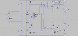
Two problems, both will blow out your added transistors:Hi Apex i would like to ad an over load short circuit protection to your Regulated PSU for my Bench power supply.
Do you thing that is correct like that, i am not sure !!!!!!View attachment 1041302
1. You need a base resistor to prevent the short from causing a huge base current when a short happens before the pass transistors can be shut off. 100 Ohms is typical.
2. This circuit has a ~large cap (100uF) in front of the 2EF. This is probably enough to blow out you added transistor when a short happens. You need a resistor to limit the current available from the 100uF caps. About 100 Ohms is probably enough, but you may want to go with as much as 330.
- Home
- Amplifiers
- Solid State
- Studio Reference Amplifier