Hi, the right approach for connecting the "ground" wire of the speaker - is to connect it directly to the main ground point at the power supply.
There's no point to connect somewhere at the amplifier board.
Cheers,
Valery
There's no point to connect somewhere at the amplifier board.
Cheers,
Valery
@ Sadik,
Maybe I'm becoming blind: where is the connector for the 'output ground' to connect the speaker? OUT only appears.
i think it is from psu gnd to speaker gnd
Today I powered on the PCB. It is working, but i am unable to set the Bais Voltage which is 20mv Across the 0.33/5watt resistors. I turn the trimmer ACW / CW (full both sides) but the bias voltage is not changing. The voltage across the 0.33/5W resistor i am getting is just 4 mV due to which the sound is not clear.
I am attaching the PCB which i am having.
Have you measured across the pot to make sure it is actually working? If the center pin is not connected to one of the other pins you will only have 1k and therefore low bias.
i think it is from psu gnd to speaker gnd
Right
Have you measured across the pot to make sure it is actually working? If the center pin is not connected to one of the other pins you will only have 1k and therefore low bias.
Yes it is connected. Do i need to change some resistor value or use higher value trimpot. Because it feels like there is no effect of the trimpot weather i rotate it in CW diection or Anti CW direction. Trimpot value i have used is "102"
Hi Sadik,
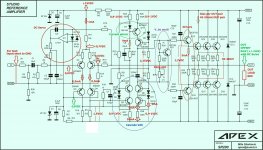
Can you please measure the voltage across R26 resistor, and then the voltage across R28 resistor (I'm looking at the schematic in post #1). We will check the VAS current that way.
Cheers,
Valery
Can you please measure the voltage across R26 resistor, and then the voltage across R28 resistor (I'm looking at the schematic in post #1). We will check the VAS current that way.
Cheers,
Valery
Today I powered on the PCB. It is working, but i am unable to set the Bais Voltage which is 20mv Across the 0.33/5watt resistors. I turn the trimmer ACW / CW (full both sides) but the bias voltage is not changing. The voltage across the 0.33/5W resistor i am getting is just 4 mV due to which the sound is not clear.
I am attaching the PCB which i am having.
I you should see this.
Attachments
Hi Sadik,
Can you please measure the voltage across R26 resistor, and then the voltage across R28 resistor (I'm looking at the schematic in post #1). We will check the VAS current that way.
Cheers,
Valery
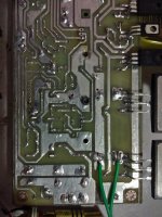
I am getting 0.091V Dc across these resistors. I am marking which resistors i measured in below image.
Attachments
Today I powered on the PCB. It is working, but i am unable to set the Bais Voltage which is 20mv Across the 0.33/5watt resistors. I turn the trimmer ACW / CW (full both sides) but the bias voltage is not changing. The voltage across the 0.33/5W resistor i am getting is just 4 mV due to which the sound is not clear.
I am attaching the PCB which i am having.
Change bd 139 resistor 1k to 1k5 and 2k trimpot
Change bd 139 resistor 1k to 1k5 and 2k trimpot
I changed as per you said but problem is not solved. Now I am changing back to original
Right
Yes it is connected. Do i need to change some resistor value or use higher value trimpot. Because it feels like there is no effect of the trimpot weather i rotate it in CW diection or Anti CW direction. Trimpot value i have used is "102"
OK so the pin is connected but if you measure across it does it change as you turn the screw?
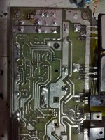
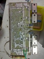
sadık can you send solder side of your board? maybe there is short at the bias pot.
I didnt find any short connection. refer the photos attached.
Whais voltage at bd139
Which points Sunny Bro
OK so the pin is connected but if you measure across it does it change as you turn the screw?
Sir, are you referring to trim-pot value or the voltage across the 0.33 ohms resistors.
Attachments
I am testing this amp with bulb in series. I was doing trouble shoot. Now i gave a grid to speakers by touching the signal in and there was a good grid in the speakers but the bulb started to glow so i switched off the amp.
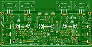
Now when speaker is not connected the bulb is not glowing. but with speaker connected the bulb is glowing. I am really getting mad. I am thinking to itch the PCB board again. This version was Sanken Transistors V 3.3 I dont think anyone has made the version 3.3 with sankens.
Can anyone guide which version of SR200 to follow if i need to itch the PCB again.
I am getting 0.091V Dc across these resistors. I am marking which resistors i measured in below image.
OK, that explains why you can't set the bias.
The VAS current is way too low. According to your measurement, you've got 0.091V/0.1K=0.91mA
Taking in account, around 1mA goes away through the diodes, you've got nothing left to drive the OPS. Correct voltage over R26, R28 would be some 0.6-0.7V (almost 10 times higher than you have now.
One more point - the fact the bulb starts glowing as soon as you connect the load tells me the amp starts oscillating with the load. But that may be caused by the issue mentioned above - too low VAS current and as a result no bias in the OPS.
Do you have an oscilloscope?
To start troubleshooting, I recommend to measure the voltages across the following resistors (with no load, no signal):
R11 -
R16 -
R17 -
R11 -
R16 -
R17 -
OK so the pin is connected but if you measure across it does it change as you turn the screw?
Hi Terry, yeah - there's practically now VAS current there, so the bias spreader is not in operation, that's the reason.
Hi Terry, yeah - there's practically now VAS current there, so the bias spreader is not in operation, that's the reason.
Hi Valery,
That makes sense. Just trying to cover the bases.
I you should see this.
Just curious, why no zobel in this amp?
- Home
- Amplifiers
- Solid State
- Studio Reference Amplifier