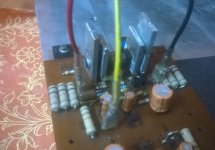
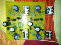
Gurpreet is there a reason for the heatsinks to be mounted differently? in the photo the ones on the left side of the board the heatsinks are in contact with the exposed metal tab on the back of the transistor but on the right they are mounted on the case side which will not properly conduct heat.
i would also make all the sinks the same size so that thermal dissipation for each device is closer to the same(can't be equal if the size is different?)
if your bias is drifting it could be thermal.
i would also make all the sinks the same size so that thermal dissipation for each device is closer to the same(can't be equal if the size is different?)
if your bias is drifting it could be thermal.
Last edited:
Gurpreet is there a reason for the heatsinks to be mounted differently? in the photo the ones on the left side of the board the heatsinks are in contact with the exposed metal tab on the back of the transistor but on the right they are mounted on the case side which will not properly conduct heat.
i would also make all the sinks the same size so that thermal dissipation for each device is closer to the same(can't be equal if the size is different?)
if your bias is drifting it could be thermal.
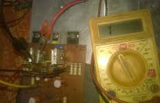
Hello my friend, thanks for help on thermal issue. Last pic click just before test, all the measure volts, bias, and DC offset(10-20mv) with proper heat sinks. No connectivity in between both sinks, its just warm. I have just two issues
1, bias stable with open input and short input with GND, but after some playing music 🎶 with 75%volume 📣 bias is shuffling and goes to 100 to 120mv.
2 , DC OFFSET not stable with short input and without short input.
Regards
Gurpreet
Attachments
Hello my friend, thanks for help on thermal issue. Last pic click just before test, all the measure volts, bias, and DC offset(10-20mv) with proper heat sinks. No connectivity in between both sinks, its just warm. I have just two issues
1, bias stable with open input and short input with GND, but after some playing music 🎶 with 75%volume 📣 bias is shuffling and goes to 100 to 120mv.
2 , DC OFFSET not stable with short input and without short input.
Regards
Gurpreet
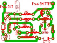
Add 100pF from base to colector on TIP142 and TIP147...

OMG, I make big mistake. I read Mr.Mile's Suggestion through email in hurry. Next I understand every suggestion then after do something, thanks Mr. Still4given you me and sr board.
Regards
Gurpreet
Regards
Gurpreet
OMG, I make big mistake. I read Mr.Mile's Suggestion through email in hurry. Next I understand every suggestion then after do something, thanks Mr. Still4given you me and sr board.
Regards
Gurpreet
You can't run the amplifier in full power having the bulb connected.
Pulb test is usefull with no signal only!
Ok Mr. Thimios ,I am agree with you on Bulb test, but I also add a two way switch between transformer to bulb and amplifier, I measures all volts in both mode ( in series and direct with main).
it's a series current limiter,no? (the dim bulb tester) what wattage of lamp are you using?
100w bulb
Add 100pF from base to colector on TIP142 and TIP147...
I think he meant to add a 100p to each from base to collector.
Now its ok?
Attachments
hi, I would like to make sr200 but among many posts and versions .. I'm a bit lost, can you help me? could you send me the files x last version with a short and psu? thank you🙂
Hello I am totally upset with me sr200 .I attach PSU grounds with input ground .When I do low volume then zzzzzzz sound coming. Sir mile plz help me .I know u r busy too much .But plz
Hello I am totally upset with me sr200 .I attach PSU grounds with input ground .When I do low volume then zzzzzzz sound coming. Sir mile plz help me .I know u r busy too much .But plz
Hi Sunny, here you are, Apex over current detected for PSU 7
Regars
Hi Sunny, here you are, Apex over current detected for PSU 7
Regars
Sorry
Attachments

Sir I need PCB layout
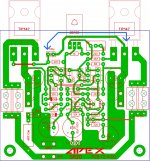
Sunny, I think u have pro adopter PCB layout, now u just compare with schematic which is posted by Kandimba.
By the way what ohm is Ur speakers 8ohm or 4ohm.
😊
Sunny, I think u have pro adopter PCB layout, now u just compare with schematic which is posted by Kandimba.
By the way what ohm is Ur speakers 8ohm or 4ohm.
😊
Sorry
Sorry 😅😅 actually last time I run my sr on 4ohm speakers now I use 8ohm speakers no hum on hiss-hiss. Thanks for noticing my attention on speaker impedance.
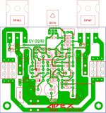
Can I use this pro adapter for sr200 with psu7
Attachments
that is a copy of my pcb that was made for apex NE555 loudspeaker protection. it was made by schematic that kandimba posted few posts earlier.
- Home
- Amplifiers
- Solid State
- Studio Reference Amplifier