Regulated PSU for Amps with 4 pairs of outputs, output voltage can be set from +/-55V to +/-90V.
Hi guys,
someone made PCB for this PSU is really interesting ...
Hi guys,
someone made PCB for this PSU is really interesting ...
Go to post #1861
sr200
hi sir mile,
my 2xSR 200 PCB are ready but have few question to you
may i ask how critical are the 3 x 470uf/100v on PCB per rail of SR200?
can i use another uf value such as 10,000uf/100v because its already available...
my OP tranies are MJL21193/4 for this project...
another question what pre amp will you recommend for SR200, is it P30Z or PP12?
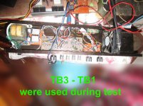
that TB3-TB1 on the pic are used during testing of previous apex amp designs both with excellent fidelity but i wanna try your SR series too...
thank you...for sharing
GOd Bless
regards
sam
hi sir mile,
my 2xSR 200 PCB are ready but have few question to you
may i ask how critical are the 3 x 470uf/100v on PCB per rail of SR200?
can i use another uf value such as 10,000uf/100v because its already available...
my OP tranies are MJL21193/4 for this project...
another question what pre amp will you recommend for SR200, is it P30Z or PP12?
that TB3-TB1 on the pic are used during testing of previous apex amp designs both with excellent fidelity but i wanna try your SR series too...
thank you...for sharing
GOd Bless
regards
sam
Attachments
is that apex mm pcb? that 470uF/100V is just addition of alex, you can omit that. also 10,000Uf.100v won't fit on the pcb.
yes sir it's Alex MM's PCB
i had just widen some areas but same size.
i am planning to have the 10,000 uf laid horizontally bracketed if necessary just to have more farad.
besides 2 x 10,000/100v is cheaper than 6 x 470/100v in my area,
thank you...
regards...
i had just widen some areas but same size.
i am planning to have the 10,000 uf laid horizontally bracketed if necessary just to have more farad.
besides 2 x 10,000/100v is cheaper than 6 x 470/100v in my area,
thank you...
regards...
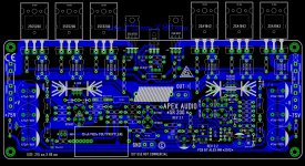
All PCBs for SR 200 IN ONE
Dear Mile Sir,
I would like to put all Circuits/ PCBs related to this amplifier APEX SR 200 in one place. Let me know if these circuits are ok to go forward for FINAL PCB work. This will help new to forum members with this design so that they can carry on the DIY work.
Mile Sir,
Please give your nod so that all PCB s are populated in correct manner.
Regards,
Samrat
Attachments
-
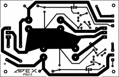 APEXaudio Reg Amp PSU PCB.jpg183.6 KB · Views: 1,431
 -
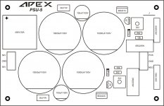 APEXaudio Reg Amp PSU MON.jpg164.3 KB · Views: 1,450
 -
Apex Regulated PSU - Nabuco Layout (3).pdf74.5 KB · Views: 518
-
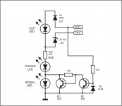 APEX signal led + clip.jpg63.9 KB · Views: 1,543
 -
APEX Speaker Terminal pdf (1).pdf25.4 KB · Views: 496
-
 SR 200 REV 3.2.jpg1,005.3 KB · Views: 1,632
 -
PCB SR 200 V3.2 SILK (1).pdf215.1 KB · Views: 465
-
PCB SR 200 V3.2 ALL (1).pdf165 KB · Views: 516
-
PCB SR 200 V3.2 (2).pdf104.6 KB · Views: 525
Dear Mile Sir,
I would like to put all Circuits/ PCBs related to this amplifier APEX SR 200 in one place. Let me know if these circuits are ok to go forward for FINAL PCB work. This will help new to forum members with this design so that they can carry on the DIY work.
Mile Sir,
Please give your nod so that all PCB s are populated in correct manner.
Regards,
Samrat
You could also add soft start and protect with psu. That would make it complete.
Yes that's true. But we require Mile Sir reply to have all sets of circuits and pcb at one place which are correct in all respect and pcb design can be perfect with out mistake.You could also add soft start and protect with psu. That would make it complete.
Mile Sir,
Please reply.
SR 200 alexmm pcb
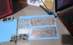
This project was started 3 years ago when I was in Dubai and I have just finished it here in Melbourne AU. Even though it took that much time to finished it but this amp makes one of my favorite as it sounds really good. thanks Apex and alexmm for a really good amp and pcb layout.😀
This project was started 3 years ago when I was in Dubai and I have just finished it here in Melbourne AU. Even though it took that much time to finished it but this amp makes one of my favorite as it sounds really good. thanks Apex and alexmm for a really good amp and pcb layout.😀
Attachments
This project was started 3 years ago when I was in Dubai and I have just finished it here in Melbourne AU. Even though it took that much time to finished it but this amp makes one of my favorite as it sounds really good. thanks Apex and alexmm for a really good amp and pcb layout.😀
Nice work.
Regards
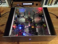
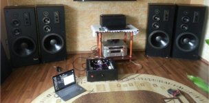
Well, I think it's time to say "Thank you Apex!" once again. I almost finished building SR-200 based power amplifier and want to share my work with you. The sound is powerful and crystal clear. My friends told me, that the music delivered by it is like discovered once again. It performs very well even on 4ohm speakers, and on 2ohm set (2xInfinity SM-155 parallel on single channel) it gets even warm at 80-90 percent output power.
Voltage rails are 2x68V (2x50VAC, 600VA shielded transformer), bias 60mA (20mV at R33 resistor). DC offset 0 to 1mV. The input stage is based on two apex TB1 modules with NE5532, since one module was unable to make SR-200 clip. Still without LOUDNESS switch. The enclosure is my own project, made from scratch.
Voltage rails are 2x68V (2x50VAC, 600VA shielded transformer), bias 60mA (20mV at R33 resistor). DC offset 0 to 1mV. The input stage is based on two apex TB1 modules with NE5532, since one module was unable to make SR-200 clip. Still without LOUDNESS switch. The enclosure is my own project, made from scratch.
Attachments
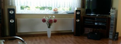
Well, I think it's time to say "Thank you Apex!" once again. I almost finished building SR-200 based power amplifier and want to share my work with you. The sound is powerful and crystal clear. My friends told me, that the music delivered by it is like discovered once again. It performs very well even on 4ohm speakers, and on 2ohm set (2xInfinity SM-155 parallel on single channel) it gets even warm at 80-90 percent output power.
Voltage rails are 2x68V (2x50VAC, 600VA shielded transformer), bias 60mA (20mV at R33 resistor). DC offset 0 to 1mV. The input stage is based on two apex TB1 modules with NE5532, since one module was unable to make SR-200 clip. Still without LOUDNESS switch. The enclosure is my own project, made from scratch.
Nice work.
Regards
SR200
greetings to all
sir miles and others...
i would like to say thank you to sir mile and alexmm and other diyers for the collaborative efforts.
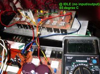
i need your help on my SR200 my question is the amp at idle dissipates much heat or it is very hot to reach more than 60 degrees or more in 20 minutes idle state without speaker or input connected to it.
i am using MJL21193/4 on outputs and have not changed other components.
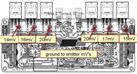
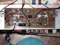
the bias current 100ma but in 3x1ohm resistors the voltage (mV) aren't the same on Ground to Emitter Q14-20mV Q16- 16mV Q18-14mV Q15-20mV Q17-17mV Q19-15mV.
DC Offset is OK about 0 to 1mV
i tried the circuit with input sound is ok. i used the same tonecontrol in testing my AX14 and B500. but with fan just to be conservative since the amp was hot even at idle.
bass was deeper than above. mid and treble are ok too.
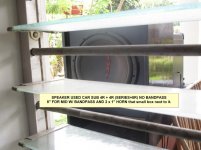
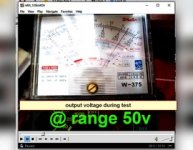
the speaker used in testing was carsub 12" XXX 4r + 4r (8ohms) 500w and 8" for mid and 2x1" horn driver. the rail voltage was +/-68 volts from 2x50VAC it clips at about 42vAC on output.
i am very satisfied with this amp my only problem was it is very hot even at idle.
pls help me out...
thank you
regards...
greetings to all
sir miles and others...
i would like to say thank you to sir mile and alexmm and other diyers for the collaborative efforts.
i need your help on my SR200 my question is the amp at idle dissipates much heat or it is very hot to reach more than 60 degrees or more in 20 minutes idle state without speaker or input connected to it.
i am using MJL21193/4 on outputs and have not changed other components.
the bias current 100ma but in 3x1ohm resistors the voltage (mV) aren't the same on Ground to Emitter Q14-20mV Q16- 16mV Q18-14mV Q15-20mV Q17-17mV Q19-15mV.
DC Offset is OK about 0 to 1mV
i tried the circuit with input sound is ok. i used the same tonecontrol in testing my AX14 and B500. but with fan just to be conservative since the amp was hot even at idle.
bass was deeper than above. mid and treble are ok too.
the speaker used in testing was carsub 12" XXX 4r + 4r (8ohms) 500w and 8" for mid and 2x1" horn driver. the rail voltage was +/-68 volts from 2x50VAC it clips at about 42vAC on output.
i am very satisfied with this amp my only problem was it is very hot even at idle.
pls help me out...
thank you
regards...
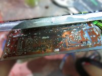
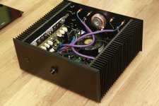
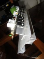
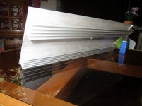
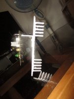
Can you show the heatsink from the other side?I think that is small.
These L bars aren't suitable for good thermal dissipation!
Emitter resistors are 0.33R not 1R.
You haven't used matched pairs,that's why different voltage measured on the emitter resistors.
Temperature rise is even worse when not matched pairs used!
Measure the temperature on transistor body,one by one,see where is the highest.
Measure the temperature directly on heat sink,compare the two values.
What is the room temperature when testing?
Last edited:
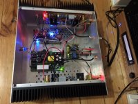
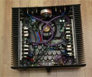
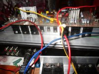
here are the pics of heatsink 4.5"x12"
ambient was 33 degrees C
that is 3x1ohm in parallel
but i don't know how to determine if paired transistor are matched, pls tell me how? coz i only learn electronic through google and youtube. but so interested to try it.
i never had this problem on ax14 and b500
thank you for helping
regards
ambient was 33 degrees C
that is 3x1ohm in parallel
but i don't know how to determine if paired transistor are matched, pls tell me how? coz i only learn electronic through google and youtube. but so interested to try it.
i never had this problem on ax14 and b500
thank you for helping
regards
Attachments
greetings to all
sir miles and others...
i would like to say thank you to sir mile and alexmm and other diyers for the collaborative efforts.
i need your help on my SR200 my question is the amp at idle dissipates much heat or it is very hot to reach more than 60 degrees or more in 20 minutes idle state without speaker or input connected to it.
i am using MJL21193/4 on outputs and have not changed other components.
the bias current 100ma but in 3x1ohm resistors the voltage (mV) aren't the same on Ground to Emitter Q14-20mV Q16- 16mV Q18-14mV Q15-20mV Q17-17mV Q19-15mV.
DC Offset is OK about 0 to 1mV
i tried the circuit with input sound is ok. i used the same tonecontrol in testing my AX14 and B500. but with fan just to be conservative since the amp was hot even at idle.
bass was deeper than above. mid and treble are ok too.
the speaker used in testing was carsub 12" XXX 4r + 4r (8ohms) 500w and 8" for mid and 2x1" horn driver. the rail voltage was +/-68 volts from 2x50VAC it clips at about 42vAC on output.
i am very satisfied with this amp my only problem was it is very hot even at idle.
pls help me out...
thank you
regards...
There is no problem, with +/-68V, 100mA and this small heatsink amp must be hot... use large heatsink or set bias to 20-30mA for test.
Regards
- Home
- Amplifiers
- Solid State
- Studio Reference Amplifier