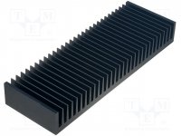
My opinion..this is a small not suitable heatsink.
Fins are horizontal and few!
You need a large one with vertical fins.
Something like this.
You must mount transistors direct on heatsink not using angle corner brackets.
If you can't find a better heatsink, lower the bias current as Mile suggest.
Fins are horizontal and few!
You need a large one with vertical fins.
Something like this.
You must mount transistors direct on heatsink not using angle corner brackets.
If you can't find a better heatsink, lower the bias current as Mile suggest.
Attachments
Last edited:
your outputs are biased to ~17mV
The bias current is ~ 0.017/0r333 = 0.051A
The dissipation in each output is ~ 68Vdc * 0.051A =~3.5W
You have six devices requiring cooling for 20.8W
They should not be getting hot.
But your heatsink is nearly useless.
And the matching between devices is pretty poor. Min = 14mV and max = 20mV, that is +43% for the hottest devices.
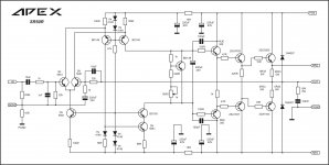
the bias current 100ma but in 3x1ohm resistors the voltage (mV) aren't the same on Ground to Emitter Q14-20mV Q16- 16mV Q18-14mV Q15-20mV Q17-17mV Q19-15mV.
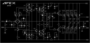
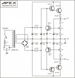
You measured voltage to GND. The sr-200 schematics shows that emitter resistors (.33ohm ones) are connected to amplifier output. So measure voltage drop on R33 resistors, between emitter and OUTPUT.
Last edited:
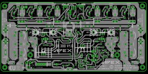
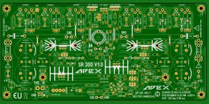
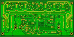
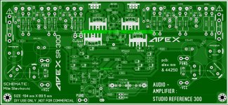
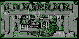
SR 300 V1.0 PCB
Hi all ,
I promise, to layout a decent PCB for SR300, so I start six or seven hour ago and this is what came out...... 😀 Not tested . PCB it's diy friendly, one layer, can be built easy.
Best regards,
Alex
Hi all ,
I promise, to layout a decent PCB for SR300, so I start six or seven hour ago and this is what came out...... 😀 Not tested . PCB it's diy friendly, one layer, can be built easy.
Best regards,
Alex
Attachments
Hi all ,
I promise, to layout a decent PCB for SR300, so I start six or seven hour ago and this is what came out...... 😀 Not tested . PCB it's diy friendly, one layer, can be built easy.
Best regards,
Alex
Nice PCB, thank you.
Regards
Excellent PCB layout. Thank you Mr. Alex and Mr. Mile Sir for sharing such wonderful designs for DIY.
I am planning to build SR-200 with three pairs of output. I wanted to know which PSU design to consider . With one pair of 2sc5200 or 2 pair of 2sc5200 for a 50-0-50 VAC , 700 VA power supply.
Please Help.
Regards,
Samrat
I am planning to build SR-200 with three pairs of output. I wanted to know which PSU design to consider . With one pair of 2sc5200 or 2 pair of 2sc5200 for a 50-0-50 VAC , 700 VA power supply.
Please Help.
Regards,
Samrat
Hi all ,
I promise, to layout a decent PCB for SR300, so I start six or seven hour ago and this is what came out...... 😀 Not tested . PCB it's diy friendly, one layer, can be built easy.
Best regards,
Alex
Nice work doctor PCB🙂
Excellent PCB layout. Thank you Mr. Alex and Mr. Mile Sir for sharing such wonderful designs for DIY.
I am planning to build SR-200 with three pairs of output. I wanted to know which PSU design to consider . With one pair of 2sc5200 or 2 pair of 2sc5200 for a 50-0-50 VAC , 700 VA power supply.
Please Help.
Regards,
Samrat
Sir,
Kindly help me - Which PSU (with one pair of 2sc5200 or 2 pair of 2sc5200) is required for SR-200 having 3 pairs of outputs.I am having Power Supply 50-0-50 VAC , 700 VA
My opinion..this is a small not suitable heatsink.
Fins are horizontal and few!
You need a large one with vertical fins.
Something like this.
You must mount transistors direct on heatsink not using angle corner brackets.
If you can't find a better heatsink, lower the bias current as Mile suggest.
your outputs are biased to ~17mV
The bias current is ~ 0.017/0r333 = 0.051A
The dissipation in each output is ~ 68Vdc * 0.051A =~3.5W
You have six devices requiring cooling for 20.8W
They should not be getting hot.
But your heatsink is nearly useless.
And the matching between devices is pretty poor. Min = 14mV and max = 20mV, that is +43% for the hottest devices.
You measured voltage to GND. The sr-200 schematics shows that emitter resistors (.33ohm ones) are connected to amplifier output. So measure voltage drop on R33 resistors, between emitter and OUTPUT.
thank you for the assistance
i will try 20-30mA while finding good heatsink and change my OP devices.
since i have been using this circuit for 2weeks @3-5 hours a day with fan.
with excellent sound quality.
thank
regards
Hi all ,
I promise, to layout a decent PCB for SR300, so I start six or seven hour ago and this is what came out...... 😀 Not tested . PCB it's diy friendly, one layer, can be built easy.
Best regards,
Alex
Your skill never seizes to amaze me 🙂
Sir,
Kindly help me - Which PSU (with one pair of 2sc5200 or 2 pair of 2sc5200) is required for SR-200 having 3 pairs of outputs.I am having Power Supply 50-0-50 VAC , 700 VA
Use PSU10 with 2 output pair.
Use PSU10 with 2 output pair.
Sir,
Thank you for the reply.
Which circuit to consider for PSU
My SR-200 has 3 pairs of output and I will use 3.2 version PCB designed by Mr.Alex.
Attachments
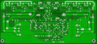
SR 300 V1.0 PDF FILES
Best regards,
Alex
I have check again and find two errors .... corrected 🙂 PDF file for tonner transfer attached. 😀Alex mm,
do you have pdf files of SR300 layout. If so, please post.
Best regards,
Alex
Attachments
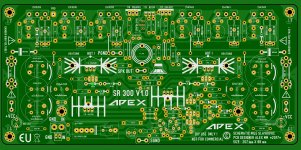
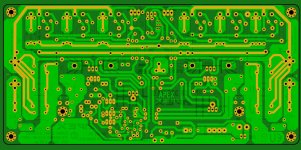
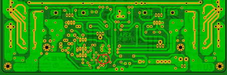
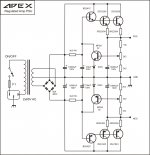
Yes it's correct , 2SK2145 it's placed on bottom side of PCB .There are two strange traces on the SR300 PCB. See the attached picture (red circle). Is that supposed to be that way?
Rick as always , my plesaure .... 😉
Regards,
Alex
- Home
- Amplifiers
- Solid State
- Studio Reference Amplifier