Hi miro1360 ,please change value for R32 in your simulation with 470K ,it's the correct one .
Regards,Alex
Regards,Alex
Hi alex, thank you. It is for both versions? In lifted ground is 470K and in normal is 470R in schematic.
And do you know which version is better to build?
And do you know which version is better to build?
Now I know, lifted ground is technique to avoid hum.
10R between SGND and PGND must be for greater loads?
10R between SGND and PGND must be for greater loads?

I'm building this PSU.
Can I use 0,33R emiter resistors instead of 0,22 and which replacements can be used for the BD240/242 combo?
Yes 0,33R will be OK, there is no overcurrent limiter. MJE15030 and MJE15031 can be used instead BD241C and BD242C.
Apex,
Thanks,In some of this PSU schematic I see the use of two 12V zeners in some of 20V is this determined by how much rail voltage you have or want?
Thanks,In some of this PSU schematic I see the use of two 12V zeners in some of 20V is this determined by how much rail voltage you have or want?
Last edited:
Apex,
Thanks,In some of this PSU schematic I see the use of two 12V zeners in some of 20V is this determined by how much rail voltage you have or want?
12v zeners is for rails about +/50v and 20v for rails about +/-80v
Dear alex mm,
Which transistor need matched pair?
If i use transfomer 55-0-55 AC then min ampe need? Capicitor for PSU min uF, V need?
Thanks you very much!
Regards, cuongdotvn
Which transistor need matched pair?
If i use transfomer 55-0-55 AC then min ampe need? Capicitor for PSU min uF, V need?
Thanks you very much!
Regards, cuongdotvn
Last edited:
A40 CFA amplifier
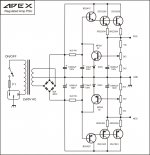
First ,input two transistors must be paired . Minimum filter capacitors 20,000uF/63v needed per positiv and negativ rail .Voltage 55-0-55 for secondary transformer it's too big ,you need only 36-0-36 V ac or maximum 38-0-38Vac and 5 to 6 A. Use 25A rectifier bridges. 🙂 .
Regards,Alex
First ,input two transistors must be paired . Minimum filter capacitors 20,000uF/63v needed per positiv and negativ rail .Voltage 55-0-55 for secondary transformer it's too big ,you need only 36-0-36 V ac or maximum 38-0-38Vac and 5 to 6 A. Use 25A rectifier bridges. 🙂 .
Regards,Alex
SR200 amp ver 3.2
Sorry, I forgot to say that I 'm using ver 3.2 SR200 circuit pcb 😛.
And I want to reach a maximum capacity of 200W / 8ohm per channel.
Thanks U.First ,input two transistors must be paired . Minimum filter capacitors 20,000uF/63v needed per positiv and negativ rail .Voltage 55-0-55 for secondary transformer it's too big ,you need only 36-0-36 V ac or maximum 38-0-38Vac and 5 to 6 A. Use 25A rectifier bridges. 🙂 .
Regards,Alex
Sorry, I forgot to say that I 'm using ver 3.2 SR200 circuit pcb 😛.
And I want to reach a maximum capacity of 200W / 8ohm per channel.
Sorry, I forgot to say that currently I 'm using version v3.2 SR200First ,input two transistors must be paired . Minimum filter capacitors 20,000uF/63v needed per positiv and negativ rail .Voltage 55-0-55 for secondary transformer it's too big ,you need only 36-0-36 V ac or maximum 38-0-38Vac and 5 to 6 A. Use 25A rectifier bridges. 🙂 .
Regards,Alex
Dear alex mm and everyone,
I 'm using version v3.2 SR200.
How much power of Zener 15V? (0.5wat ?)
How much volt transformer is maximum for pcb if i use power supply non regulator?
And volt minimum of Capicitor:
- 100pF
- 470pF
- 22nF
if i use +-75vdc?
Thanks!!! Sorry, my english is very bad 🙁.
Regards, cuongdotvn
I 'm using version v3.2 SR200.
How much power of Zener 15V? (0.5wat ?)
How much volt transformer is maximum for pcb if i use power supply non regulator?
And volt minimum of Capicitor:
- 100pF
- 470pF
- 22nF
if i use +-75vdc?
Thanks!!! Sorry, my english is very bad 🙁.
Regards, cuongdotvn
Dear, still4giventest
Srorry!!! I don't understand. 😡
Regards, cuongdotvn
Can I use this PSU 10 for a Class A amp like the F5?
Yes with outputs on heatsink.
- Home
- Amplifiers
- Solid State
- Studio Reference Amplifier