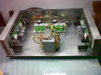
My Sr200 ...not 100% finished, still waiting for proper transformer ....
cool Man 🙂
My Sr200 ...not 100% finished, still waiting for proper transformer ....
you really know how to DIY ,excellent!
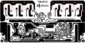
studio reference with to3 output transistors,pcb done by member d.veljkovic:
Attachments
Last edited:
all better characteristics of to3 transistors are transfered to an amplifier it self,the basic pcb is from alex mm,his version 3.1.
studio reference with to3 output transistors,pcb done by member d.veljkovic:
What is the recommended TO-3 output transistors? good layout by the way
 .
.that is to be gratefull to alex mm and d.veljko! 🙂
recommended would be bipolar transistors with same or higher voltage,power and hFE. i believe that Mile-APEX could give a more specific list of transistors,i don´t have that experience to do so...
recommended would be bipolar transistors with same or higher voltage,power and hFE. i believe that Mile-APEX could give a more specific list of transistors,i don´t have that experience to do so...
studio reference with to3 output transistors,pcb done by member d.veljkovic:
here is jpg. too:
Attachments
My Sr200 ...not 100% finished, still waiting for proper transformer ....
Nice amp with regulated PSU,
Regards
studio reference with to3 output transistors,pcb done by member d.veljkovic:
Nice work, I suggest to use MJE15024/15025,
Regards
Nice work, I suggest to use MJE15024/15025,
Regards
does not modify the voltage; 😕😕
Nice amp with regulated PSU,
Regards
Thank you so much Mr. Mile Slavkovic...very good design you have...I still need your advice...
Best Regards
here is jpg. too:
Can u Share to me for Top Layer and Buttom Layer format PDF.
regards.
Can u Share to me for Top Layer and Buttom Layer format PDF.
regards.
I would like to have information on this PCB:
APEX B500
Not if you will have in pdf side copper components, the diagram, pcb size
😕,😕,😕,😕
Attachments
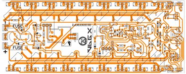
I would like to have information on this PCB:
APEX B500
Not if you will have in pdf side copper components, the diagram, pcb size
😕,😕,😕,😕
I'll Share with you, you must give in order to relay protector speaker module can work as protect.
Attachments
Can u Share to me for Top Layer and Buttom Layer format PDF.
regards.
post 885,i don't have layout pdf.
Thank you so much Mr. Mile Slavkovic...very good design you have...I still need your advice...
Best Regards
I suggest set bias to 20-30mA per pair (600-900mV at 10R instead fuse). With 50mA per pair you have over 20W disipation per channel it's too high for your small heatsinks.
Regards
I'll Share with you, you must give in order to relay protector speaker module can work as protect.
sir Damanhuri
nice PCB ,what is the out put power in (8ohm,4 ohm, if it can drive in 2ohm) this you'r new B50 pcb layout with 9 pair power transistor & what is the +/- DC v
thanks
nuwan
- Home
- Amplifiers
- Solid State
- Studio Reference Amplifier