Farnell also has Dale RN60D. I bought mine from them. But, after all that soldering that you already done Michael, think again😀
Btw, nice work Michael 😉
Btw, nice work Michael 😉
Farnell also has Dale RN60D. I bought mine from them. But, after all that soldering that you already done Michael, think again😀
Btw, nice work Michael 😉
Thanks for the tip Dean! Hahaha 😀 Will be a lot of work indeed. Hmm, Dean do you think Dale resistors will offer benefits? I can understand that maybe dc offset will be slightly lower, although dc offset could be dialed down to 0 mV with the little trimpot. The resistors I currently use are rated for 0.6 W, have metal film, and most have a tolerance of 1%, but a few are 5%. They are from an unkwnown brand, so I assume they haven't got special properties. Could they influence the sound in a negative way on a scientific basis?
To be honest, I can't hear the difference between Dale and other resistor brands. I think this is a more in psichology sphere😀. Dale's are low noise, military grade resistors, which is good, but will you benefit from them is really hard to say. Krell has DC offset tolerance 30mV, so I think yours is OK 😉
Btw, there's a lot of better resistors on the market...if the price is no object😀
Btw, there's a lot of better resistors on the market...if the price is no object😀
Relays
Are you planning to manufacture your creation? It is beautiful. No one will be able to follow this act. I have one little question about the soft-start and the speaker protections. I how much amperage do you think they will pull? I was thinking at least 1 amp for each relay?Thanks for the tip Dean! Hahaha 😀 Will be a lot of work indeed. Hmm, Dean do you think Dale resistors will offer benefits? I can understand that maybe dc offset will be slightly lower, although dc offset could be dialed down to 0 mV with the little trimpot. The resistors I currently use are rated for 0.6 W, have metal film, and most have a tolerance of 1%, but a few are 5%. They are from an unkwnown brand, so I assume they haven't got special properties. Could they influence the sound in a negative way on a scientific basis?
Thanks Dean. Haha pfew, so changing the resistors is not going to give that much difference. That is great news 😀
@ Spurtle: 1 A for the relaiys is more than enough, if you want you can use a transformer that can handle far more less current. By the way, you dont need another transformer for the softstart; it has already mounted a transformer to the PCB 🙂 The little transformer which is mounted at the softstart PCB is 1 VA (or Watt, because volt * amp gives watt) @ 2x 12 VAC. So the current it can deliver is about 2x 41,66 mA @ 12 VAC. I dont know how much current the relays on the softstart PCB precisely will draw, and how much the electronics around it will use, but I think it should be around 35 mA per relay.
For the speaker protection I use a tiny 2x 12VAC 1.2VAC transformer. The relays I use (Omron GR2L) draw 32 mA per relay to power the coil and thus to switch. Works like a charm. But be carefull, those little PCB-transformers are not very efficiënt, so you have to choose a transformer that can deliver lets say 10% more so the core of the transformer does not get saturated to fast. Then it gets warm and will vanish not into thin air but black smoke instead 😀 If I am correct the transformers you showerd earlier (nice ones btw!!!) have already a 12V winding to it. That would be perfect, because you than don't have to mount extra transformers (like I had to).
Haha who knows what the future will bring David 😉 Would love to manufacture amplifiers. Too bad my study takes a lot of my time away. Sometimes there are moments were you have to study for 50 hours a week. But that is mainly when I realise that the exam week is only 2 weeks away, and I haven't made any excersises thusfar haha.
Thanks for the compliments!!! I really like the way things turn out. Want to get it perfect, but that is also a weakness of me. I am a bit of a perfectionist, so even when things work, it could be better (like my idea to change the resistors haha). But it adds to the fun.
By the way, I bought something, which I think, is really nice, a little amplifier PCB with 2SJ49/2SK134 for the Goldmund clone!!!! Paid 50 euro's. Would that be a reasonable price? The amplifier is called a albs SyMOS 300. Never heard of it. Has somebody experience with it. It will take a long long time before I start with this clone, but preparation has just started 😀
Picture of it:
An externally hosted image should be here but it was not working when we last tested it.
Counselor
Thanks Dean. Haha pfew, so changing the resistors is not going to give that much difference. That is great news 😀
@ Spurtle: 1 A for the relaiys is more than enough, if you want you can use a transformer that can handle far more less current. By the way, you dont need another transformer for the softstart; it has already mounted a transformer to the PCB 🙂 The little transformer which is mounted at the softstart PCB is 1 VA (or Watt, because volt * amp gives watt) @ 2x 12 VAC. So the current it can deliver is about 2x 41,66 mA @ 12 VAC. I dont know how much current the relays on the softstart PCB precisely will draw, and how much the electronics around it will use, but I think it should be around 35 mA per relay.
For the speaker protection I use a tiny 2x 12VAC 1.2VAC transformer. The relays I use (Omron GR2L) draw 32 mA per relay to power the coil and thus to switch. Works like a charm. But be carefull, those little PCB-transformers are not very efficiënt, so you have to choose a transformer that can deliver lets say 10% more so the core of the transformer does not get saturated to fast. Then it gets warm and will vanish not into thin air but black smoke instead 😀 If I am correct the transformers you showerd earlier (nice ones btw!!!) have already a 12V winding to it. That would be perfect, because you than don't have to mount extra transformers (like I had to).
Haha who knows what the future will bring David 😉 Would love to manufacture amplifiers. Too bad my study takes a lot of my time away. Sometimes there are moments were you have to study for 50 hours a week. But that is mainly when I realise that the exam week is only 2 weeks away, and I haven't made any excersises thusfar haha.
Thanks for the compliments!!! I really like the way things turn out. Want to get it perfect, but that is also a weakness of me. I am a bit of a perfectionist, so even when things work, it could be better (like my idea to change the resistors haha). But it adds to the fun.
By the way, I bought something, which I think, is really nice, a little amplifier PCB with 2SJ49/2SK134 for the Goldmund clone!!!! Paid 50 euro's. Would that be a reasonable price? The amplifier is called a albs SyMOS 300. Never heard of it. Has somebody experience with it. It will take a long long time before I start with this clone, but preparation has just started 😀
Picture of it:
An externally hosted image should be here but it was not working when we last tested it.
Where did you get the PCBs? Mine if I tagged along? What kind of power supply are needed? Now here's the big question. Will you start a new thread for the Goldmund?
Where did you get the PCBs? Mine if I tagged along? What kind of power supply are needed? Now here's the big question. Will you start a new thread for the Goldmund?
Haha, sure thing Spurtle! When I start this new project I will certainly open a new topic 😀 I almost have to because I need the expertise and comments from you all. But first..... we have to finish the Krell 😀
I bought the PCB in the picture from a sir from Amsterdam. I haven't received the PCB yet, but I think I will receive the PCB (with the trannies) next week. I initially bought the PCB for the MOSFET's which I could use for the Goldmund clone. The 2SJ49 / 2SK134 are pretty hard to find and.... very expensive. So when I saw this PCB on Marktplaats (Dutch equivalent of ebay) I sended the vendor an e-mail. Paid about 61 dollars for it (50 euro's), which is far more less than the market value of the trannies alone (if I compaire to what some webshops charge, and then you have to hope you will have the real deal and not fakes).
I came to know a bit more of this PCB. It was made in the 80's, datasheet says 1984 (I was not even born back then 😀). It was made by a company in Germany called ALBS (Alltronic Balthasar Schmidt) which sold back in the day high end DIY-kits. A bit like Hypex now. It can deliver 300W @ 4 ohms, 200 W @ 8 ohms). When the 2SJ49 / 2SK134 dissapeared, so did the company. Although they are offering right now sort of the same kits with replacement FET's (BUZ900 BUZ905). I discovered this kit is actually pretty good and was pretty expensive. Here is the datasheet: http://michaelq.home.xs4all.nl/Datasheets/MOS100-300_1981-85.pdf (I have the MOS 300N). It is in German, leider ist mein Deutsch nicht so gut, but, it needs 750VA per channel and +/- 50VDC. Too bad I have only one kit. Maybe I search for another same kit. Am curious to the sound. And the more I get to know about it, the less I want to take the MOSFET's out of it for the Goldmund. Maybe I build an ALBS instead 😀
Funny, I spent 2 years in Wurzburg, Germany with an Army signal company 1973-75. Had a wonderful time. Went back five years ago to visit German friends. Please let me know if you can find another kit, will you? Take your time as we must finish the Krell.Haha, sure thing Spurtle! When I start this new project I will certainly open a new topic 😀 I almost have to because I need the expertise and comments from you all. But first..... we have to finish the Krell 😀
I bought the PCB in the picture from a sir from Amsterdam. I haven't received the PCB yet, but I think I will receive the PCB (with the trannies) next week. I initially bought the PCB for the MOSFET's which I could use for the Goldmund clone. The 2SJ49 / 2SK134 are pretty hard to find and.... very expensive. So when I saw this PCB on Marktplaats (Dutch equivalent of ebay) I sended the vendor an e-mail. Paid about 61 dollars for it (50 euro's), which is far more less than the market value of the trannies alone (if I compaire to what some webshops charge, and then you have to hope you will have the real deal and not fakes).
I came to know a bit more of this PCB. It was made in the 80's, datasheet says 1984 (I was not even born back then 😀). It was made by a company in Germany called ALBS (Alltronic Balthasar Schmidt) which sold back in the day high end DIY-kits. A bit like Hypex now. It can deliver 300W @ 4 ohms, 200 W @ 8 ohms). When the 2SJ49 / 2SK134 dissapeared, so did the company. Although they are offering right now sort of the same kits with replacement FET's (BUZ900 BUZ905). I discovered this kit is actually pretty good and was pretty expensive. Here is the datasheet: http://michaelq.home.xs4all.nl/Datasheets/MOS100-300_1981-85.pdf (I have the MOS 300N). It is in German, leider ist mein Deutsch nicht so gut, but, it needs 750VA per channel and +/- 50VDC. Too bad I have only one kit. Maybe I search for another same kit. Am curious to the sound. And the more I get to know about it, the less I want to take the MOSFET's out of it for the Goldmund. Maybe I build an ALBS instead 😀
***
By the way, I bought something, which I think, is really nice, a little amplifier PCB with 2SJ49/2SK134 for the Goldmund clone!!!! Paid 50 euro's. Would that be a reasonable price? The amplifier is called a albs SyMOS 300. Never heard of it. Has somebody experience with it. It will take a long long time before I start with this clone, but preparation has just started 😀
Picture of it:
An externally hosted image should be here but it was not working when we last tested it.
Back when I was into all this audio stuff I not only did DIY but also had quite a bit of high end equipment from all over (Utah and Switzerland included). Liked the Krell clone better than the Mimesis 28; it had slightly more noise but far better impact and "live" sound.
http://www.diyaudio.com/forums/multi-way/69687-does-wilson-audio-know-what-they-aredoing-9.html#post793687
Last edited:
Liked the Krell clone better than the Mimesis 28;
That is very reassuring as there will be long before I hear this kitten purr. 😛
Back when I was into all this audio stuff I not only did DIY but also had quite a bit of high end equipment from all over (Utah and Switzerland included). Liked the Krell clone better than the Mimesis 28; it had slightly more noise but far better impact and "live" sound.
http://www.diyaudio.com/forums/multi-way/69687-does-wilson-audio-know-what-they-aredoing-9.html#post793687
Do you still have that amp Greeny ...?
Do you still have that amp Greeny ...?
No, got out of audio and sold all of it. All that is left is 1 set of speakers, 1 amp, 1 preamp, 1 turntable, 1 tuner, 1 DAC (for the PC), all of which are commercial units. Still have all my diy projects which are connected up a few times a year to evaluate operational status and reflect on the good times here. Actually I am using DIY/commercial about 60/40 but cannot explain why (maybe nervous about my construction quality?)
It was great fun playing around with high end audio for 10+ years, sold most everything (including this amp) for what I paid for it despite using the equipment for 1-2 years. Was able to do this because I bought everything used and watched audiogon constantly to keep up on good price points. Only took losses on the CD players. Never had a component fail or break either. Ever. (DIY or commercial). Fun for a long time but now on to other things.
EDIT- Just remembered shorting an output stage on a DIY amp but replaced the parts and it was good to go.
Last edited:
Thanks for your sharing your experience lgreen! So I did a good investment in building a Krell 😀 I am very curious to the 'sound' of a Goldmund. Never heard one in my entire life.
Sorry for going a bit off-topic, but meine damen und herren, I received the ALBS-kit. It is a very nice PCB. The vendor dispached a bunch of capacitors with it for free. Nice 10000uF / 80V electrolytic caps. Okay, capacity is a bit less because of aging, but hey you don't look a given horse in the mouth.
The ALBS-amplifier works! Tested it while using the Krell clone PSU (+/- 52VDC). First impressions, well if I have to be honest, the sound is a bit dissapointing. You absolutely can't compaire it with the Krell Clone. I miss the so called slam. Also clairity of the instruments is not very good. It is a bit like a PA-amplifier, it goes very loud, but lack of detail and dynamics. But hey, there can be done a lot of tweaking like changing the caps. I am very curious if I can make the design better. Bottom line is the MOSFETS are okay, and that is the most important part for me 🙂
Picture of the test setup:
Sorry for going a bit off-topic, but meine damen und herren, I received the ALBS-kit. It is a very nice PCB. The vendor dispached a bunch of capacitors with it for free. Nice 10000uF / 80V electrolytic caps. Okay, capacity is a bit less because of aging, but hey you don't look a given horse in the mouth.
An externally hosted image should be here but it was not working when we last tested it.
The ALBS-amplifier works! Tested it while using the Krell clone PSU (+/- 52VDC). First impressions, well if I have to be honest, the sound is a bit dissapointing. You absolutely can't compaire it with the Krell Clone. I miss the so called slam. Also clairity of the instruments is not very good. It is a bit like a PA-amplifier, it goes very loud, but lack of detail and dynamics. But hey, there can be done a lot of tweaking like changing the caps. I am very curious if I can make the design better. Bottom line is the MOSFETS are okay, and that is the most important part for me 🙂
Picture of the test setup:
An externally hosted image should be here but it was not working when we last tested it.
You are very busy these days Michael... that's very good 😉
...but finish that Krell monster first😀
...but finish that Krell monster first😀
Haha yes, that seems like a pretty big transformer. That transformer should have no problem delivering enough current. But I am afraid they don’t aflote, so you can’t use them as tug boat with spring break arrives haha 😀
Actually it surprises me that my KSA-100 does not draw that much current from the mains. My amp meter says 1.2 A @232VAC, so about 280W. That’s far more less than the air conditioner which is needed to cool the room down 😎
I made some progress aswell,. Will post some pictures of the KSA soon. Battery is low, so I have to charge them.
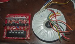
Dean, I bought some Dale resistors and replaced some of the original ones Haha, I HAD to try 😀. To be fair, I can’t hear any difference between a board with Dale resistors and a board which still had the resistors on them which I soldred earlier. From the other hand, I have to say, the quality of the Dale’s is much, much higher. They are more rigid, leads are thicker and far much lower tolerances than the ones I soldred earlier when comparing values. I am happy with them.
I have also mounted the board to the cooling tunnels, wired the fuse box and wired the boards to the trannies. I used this config first:
Although I thought it looked very nice, I realised this was actually not preferable. Leads to the trannies were far more longer than when I would rotate the boards 90 degrees. So had to make a new plate and drill new holes, so I could rotate the boards 90 degrees… but I was bored anyway 😉
When testing the amplifier, it is even better! Previously when I cutted the power towards the amplifier there erupted a sort of oscillation, almost like a little canary flute, but there was not a canary here! Now the amp shuts down like it should, it keeps on playing for another 10 secs, sounds fades away and than gets distorted because the caps are at that moment almost discharged. Unbelievable how much current these caps can deliver.
But I have some questions which I REALLY hope someone can help me, yes some of you already predicted it, it gets HOT, yes like in the song from Arrow - HOT! HOT! HOT! For the fans: http://www.youtube.com/watch?v=OkGgdIBX1to
I attached a thermostat to the heatsinks with some thermal grease. When applying 500mV the thermostats (rated 75 degrees) kick after 30 mins in and would, if I had connected them, shut the amplifier down. The hottest part of the heatsink (at the end of the tunnel) gets about 40 / 45 degrees above ambient temperature when fan speed @50 % and bias @ 400 mV. The least hot part of the heatsink gets about 30 / 35 above ambient temperature.
But friends, what is safe? I’ve red the original KSA-100 uses 100 degrees thermostats. This would mean TO3 devices can reach 100 degrees before it cuts the power. Also heatsinks on the original KSA-100 are smaller than mine. From the other hand they are separated from each other which is better.
I use anodized heatsinks, the TO3 devices are directly attached (with a very thin layer of thermal grease) to the heatsink, so better thermal attachment than this is not possible.
How can I calculate how high the temperature may become? I know Tj can be max 200 degrees Celsius. I also know thermal resistance, junction to case is max 0,70 C/W. Rail voltage is + / - 51 VDC
I found this formula in the other KSA-threat: Tc = Tj - Tjc * P
Tc = 200, but let’s be on the safe side, 150 it is. Temperature in my case at, let’s say 75 degrees:
75 = 150 - 0,7 * X, so the power it can handle 107 W per device max? I don't really understand how to calculate it.
Actually it surprises me that my KSA-100 does not draw that much current from the mains. My amp meter says 1.2 A @232VAC, so about 280W. That’s far more less than the air conditioner which is needed to cool the room down 😎
I made some progress aswell,. Will post some pictures of the KSA soon. Battery is low, so I have to charge them.
Dean, I bought some Dale resistors and replaced some of the original ones Haha, I HAD to try 😀. To be fair, I can’t hear any difference between a board with Dale resistors and a board which still had the resistors on them which I soldred earlier. From the other hand, I have to say, the quality of the Dale’s is much, much higher. They are more rigid, leads are thicker and far much lower tolerances than the ones I soldred earlier when comparing values. I am happy with them.
I have also mounted the board to the cooling tunnels, wired the fuse box and wired the boards to the trannies. I used this config first:
An externally hosted image should be here but it was not working when we last tested it.
Although I thought it looked very nice, I realised this was actually not preferable. Leads to the trannies were far more longer than when I would rotate the boards 90 degrees. So had to make a new plate and drill new holes, so I could rotate the boards 90 degrees… but I was bored anyway 😉
When testing the amplifier, it is even better! Previously when I cutted the power towards the amplifier there erupted a sort of oscillation, almost like a little canary flute, but there was not a canary here! Now the amp shuts down like it should, it keeps on playing for another 10 secs, sounds fades away and than gets distorted because the caps are at that moment almost discharged. Unbelievable how much current these caps can deliver.
But I have some questions which I REALLY hope someone can help me, yes some of you already predicted it, it gets HOT, yes like in the song from Arrow - HOT! HOT! HOT! For the fans: http://www.youtube.com/watch?v=OkGgdIBX1to
I attached a thermostat to the heatsinks with some thermal grease. When applying 500mV the thermostats (rated 75 degrees) kick after 30 mins in and would, if I had connected them, shut the amplifier down. The hottest part of the heatsink (at the end of the tunnel) gets about 40 / 45 degrees above ambient temperature when fan speed @50 % and bias @ 400 mV. The least hot part of the heatsink gets about 30 / 35 above ambient temperature.
But friends, what is safe? I’ve red the original KSA-100 uses 100 degrees thermostats. This would mean TO3 devices can reach 100 degrees before it cuts the power. Also heatsinks on the original KSA-100 are smaller than mine. From the other hand they are separated from each other which is better.
I use anodized heatsinks, the TO3 devices are directly attached (with a very thin layer of thermal grease) to the heatsink, so better thermal attachment than this is not possible.
How can I calculate how high the temperature may become? I know Tj can be max 200 degrees Celsius. I also know thermal resistance, junction to case is max 0,70 C/W. Rail voltage is + / - 51 VDC
I found this formula in the other KSA-threat: Tc = Tj - Tjc * P
Tc = 200, but let’s be on the safe side, 150 it is. Temperature in my case at, let’s say 75 degrees:
75 = 150 - 0,7 * X, so the power it can handle 107 W per device max? I don't really understand how to calculate it.
Last edited:
Klapaars, are you using the push-pull fan setup? One fan pushing cool air in the tunnel on one end and the other fan, at the other end, pulling hot air out of the tunnel. Could this setup average out the temperature differences across the tunnel? I, just got home for the supply store, just bought two 120VAC, Artic Air 11.5mm dia. fans. Since I am building mono-blocks, I now feel I will need to extra fans to do the push-pull setup. You have 51VDC on the rails, I will have 56.56VDC. HOT, HOT, HOT! Stuart Easson warned me and made a suggestion for 35VAC transfos.
Hi Spurlte
If you are running two separate fans you should not have a problem.
I suspect the moment Kaplaars has two independent vertical fans his problem wil be solved as his heatsinks are larger than the original model used by Krell. But that means a possible new box or two box design for our young builder.
Regards
Jozua
Hi guys,
I've done some further measures and digested some reading food 😀 I've experienced that airflow is actually decreased with the push pull system. It seems that the outtake fan is blocking air that is blown towards this fan. I got more airflow when using one fan. Unfortunatelly haven't got a nice temperature meter, otherwise I could measure temperature more accurately and see if there is a difference in temperature.
Temperature difference between the outher sections is about 10 / 15 degrees. I used the so called 'finger method'. When you can put you finger on the heatsink for more than 30 seconds, temperature is about 60 degrees (or less). I can do this at the intake, but not at the outtake (which is about 75 degrees).
Now it is really hot here in Holland, especially at my room, it is a great time to test for extreme circumstances. Actually I don't experience sonic difference between 400 or 625 mV bias, so that is a good thing. Would also be logical, because bias has to be slightly more than than the power the amplifier has to deliver at that moment. Since I don't listen at very high volumes, using too much bias would actually be wasting energy.
But aside from that, this stuff strongly appeals to me, so I realy want to know how it works 🙂 I've done some calculations, hear me out :
1. Total dissipation: since it is class A, the more power your speakers absorb, the less heat, because power is now not dissipated, but used as sonic power. So total dissipation is (I think) (railvoltage (VDC) * bias (ampère)) - ((output voltage (AC) * sqrt(2))^2 / load (ohms)). I assume there is no load from here, all power is transfered into heat, so 51 * 0,4 = 20.4 W per device.
2. So total dissipation per channel = 8 * 20.4 = 166,4 W
3. dT = Theatsink - Tambient = 75 - 30 = 45 degrees Celcius.
4. C/W - value of the heatsinks is thus: 45 / 166,4 = 0,27
5. Tr from MJ15003/4 = 0,7 C/W, C/W heatsink = 0,27, so total = 0,97 --> so 0,97 * 0,4 * 51 = 19,8 C. Temperatur inside is thus 75 + 19,8 = 94.8 degrees. Yes, that is hot, but far under 200 degrees for Tj.
If the above is correct is isn't that hard to calculate max bias:
Lets say Tjmax is allowed to be 150 degrees to be safe.
bias (mV) * 51 * .97 + .7 * bias (mv) * 51 = 150 degrees C.
bias (mV) * 49.47 + 35.7 * bias (mv) = 150
bias (mV) * 85.17 = 150
bias (mV) = 150/85.17 so bias can maximally be 1,76 V.
Big chance I did something wrong 😀 Hope someone can guide me on the right track.
Edit: typoooo
Last edited:
- Home
- Amplifiers
- Solid State
- Stolen Trademark Amplifier from Jim's Audio on EBAY