Yes, creepy nightwalkers are not allowed in my amplifier ;-) Only joking, but the resistors should damp distortion which can travel via GND into your amplifier bit.
I use star ground. All the devices that have to be connected to ground, like the shield around the signalcables, the minus leads of the speaker terminals, earth GND from the wall outlet and so on are connected to the little groundplane. The little groundplane itself is connected to the chassis. So actually all ground leads come together in one point. This is what is called star grounding. Correct grounding is VERY important for a stable, hum free amplifier. Here is some more interesting info: Earthing (Grounding) Your Hi-Fi - Tricks and Techniques
but if there is a foult, and the ground is conducting. the resistors will burn and you loose the earthground.
CL-60 kan handle 5amps. and loose resistanse when heating up. much safer🙂
but if there is a foult, and the ground is conducting. the resistors will burn and you loose the earthground.
CL-60 kan handle 5amps. and loose resistanse when heating up. much safer🙂
Hmm, that is indeed a smart solution! In my build I use 5 W, 10 ohms resistors, so they can dissipate, in case of short circuit, just enough before they burn up. This should give enough time for the RCD to intervene, but indeed better safe than sorried.
Groundplane
Is there a way to use both? Or would that cause the current to favor one component over the other for least resistance.Hmm, that is indeed a smart solution! In my build I use 5 W, 10 ohms resistors, so they can dissipate, in case of short circuit, just enough before they burn up. This should give enough time for the RCD to intervene, but indeed better safe than sorried.

I think it is best to use one of them. The NTC would be the smartest solution when you choose a CL-60 which is 10 ohms. When you choose a NTC that has a higher resistance the resistor will be a better choise because because it takes time for the NTC to heat up and thus lower it's resistance.
I found out that adding a resistor in series with any kind of GND is actually forbidden in consumer electronics here in Holland. All the minus leads have to be directly connected to ground. I think the very best solution would be this network:
But it makes the build more complex. I like the KISS rule (Keep It Simple Stupid). So I think I stick to using an NTC, and thus a resistor in my design. After all it still is favorable to use a ground loop breaker for example a resistor, than using none.
I have by the way a question about grounding too 🙂 I use live heatsinks, so they can't be connected to ground. But I've red this could cause oscillation. It is always best to ground the heatsinks. Could this be true?
I think the square wave test AVWERK posted about give more information about possible instability. Realy curious how this test will turn out. I have to make a square wave generator by the way because my computer is not able to make nice square waves because of it's limited bandwith (96kHz).
By the way; little sidenote has anybody compared a KSA-100 to the Goldmund mimesis 9.2? I've red about this design, and I was very impressed. Maybe Kaplaars has already another project for when the KSA-100 clone is finished haha.
Edit: nice capacitors Spurtle! I use sort of the same. Mine are also rated for 85 degrees. I have Nippon Chemicons (44000 uF). The original KSA-100 uses 85 degree rated caps too, so I think it's OK.
I found out that adding a resistor in series with any kind of GND is actually forbidden in consumer electronics here in Holland. All the minus leads have to be directly connected to ground. I think the very best solution would be this network:
An externally hosted image should be here but it was not working when we last tested it.
But it makes the build more complex. I like the KISS rule (Keep It Simple Stupid). So I think I stick to using an NTC, and thus a resistor in my design. After all it still is favorable to use a ground loop breaker for example a resistor, than using none.
I have by the way a question about grounding too 🙂 I use live heatsinks, so they can't be connected to ground. But I've red this could cause oscillation. It is always best to ground the heatsinks. Could this be true?
I think the square wave test AVWERK posted about give more information about possible instability. Realy curious how this test will turn out. I have to make a square wave generator by the way because my computer is not able to make nice square waves because of it's limited bandwith (96kHz).
By the way; little sidenote has anybody compared a KSA-100 to the Goldmund mimesis 9.2? I've red about this design, and I was very impressed. Maybe Kaplaars has already another project for when the KSA-100 clone is finished haha.
Edit: nice capacitors Spurtle! I use sort of the same. Mine are also rated for 85 degrees. I have Nippon Chemicons (44000 uF). The original KSA-100 uses 85 degree rated caps too, so I think it's OK.
Last edited:
Yes, I took my time in looking for the right caps for the right price. Lucked out with a chap on eBay. His store is "capacitor12." The four costs $105 USA. Every other electronic store wanted much more for the high capacitance and voltage. Kaplaars, I looked at the schematic for the "ExtremeA Power Wiring," it shows to apply a .047uF cap accross the positive wire, on the mains immediately after the fuse/switch and before the terminal block and the neutral wire. How high, in voltage, should this .047uF polarized capacitor be? Also, this diagram shows CL-60s for the chassis ground (one) and 2, in series for both high power transformer (positive primary) in parallel. As this is my first major high powered power supply, I want build a separate chassis for the power supply--something like you preamp. Do you see any forseeable problem with this setup? I received all my speaker protection and your suggested soft-starts with temp sensors. The fastest delivery so far. Now for the fire extinguisher!I think it is best to use one of them. The NTC would be the smartest solution when you choose a CL-60 which is 10 ohms. When you choose a NTC that has a higher resistance the resistor will be a better choise because because it takes time for the NTC to heat up and thus lower it's resistance.
I found out that adding a resistor in series with any kind of GND is actually forbidden in consumer electronics here in Holland. All the minus leads have to be directly connected to ground. I think the very best solution would be this network:
An externally hosted image should be here but it was not working when we last tested it.
But it makes the build more complex. I like the KISS rule (Keep It Simple Stupid). So I think I stick to using an NTC, and thus a resistor in my design. After all it still is favorable to use a ground loop breaker for example a resistor, than using none.
I have by the way a question about grounding too 🙂 I use live heatsinks, so they can't be connected to ground. But I've red this could cause oscillation. It is always best to ground the heatsinks. Could this be true?
I think the square wave test AVWERK posted about give more information about possible instability. Realy curious how this test will turn out. I have to make a square wave generator by the way because my computer is not able to make nice square waves because of it's limited bandwith (96kHz).
By the way; little sidenote has anybody compared a KSA-100 to the Goldmund mimesis 9.2? I've red about this design, and I was very impressed. Maybe Kaplaars has already another project for when the KSA-100 clone is finished haha.
Edit: nice capacitors Spurtle! I use sort of the same. Mine are also rated for 85 degrees. I have Nippon Chemicons (44000 uF). The original KSA-100 uses 85 degree rated caps too, so I think it's OK.
That .047 uF cap in the ExtremA diagram is actually non-polarized AC Line quality cap X or Y (or something, I forget). It is there to shunt HF noise out of the line. And its only there because its in some of the Nelson Pass amp designs, so I just threw it in.
The real concern here is arcing of the on/off switch. Wondering how you all will address that?
I put a cap across the switch terminals but again, just because I saw it done before. Not sure I understand the operation of it.
See another power diagram (this one of the Krell) here showing this cap C1 (also AC line rated)-
Krell Power Diagram
EDIT- yes it is possible that with live heatsinks you can pick up some noise on your heatsinks. I didn't see this on mine but it is another reason not to use live heatsinks. I suppose you just need to be careful routing and shielding everything - which it seems you are an expert at so I am not worried about this in your situation.
Last edited:
Yes, I took my time in looking for the right caps for the right price. Lucked out with a chap on eBay. His store is "capacitor12." The four costs $105 USA. Every other electronic store wanted much more for the high capacitance and voltage. Kaplaars, I looked at the schematic for the "ExtremeA Power Wiring," it shows to apply a .047uF cap accross the positive wire, on the mains immediately after the fuse/switch and before the terminal block and the neutral wire. How high, in voltage, should this .047uF polarized capacitor be? Also, this diagram shows CL-60s for the chassis ground (one) and 2, in series for both high power transformer (positive primary) in parallel. As this is my first major high powered power supply, I want build a separate chassis for the power supply--something like you preamp. Do you see any forseeable problem with this setup? I received all my speaker protection and your suggested soft-starts with temp sensors. The fastest delivery so far. Now for the fire extinguisher!
Wow those caps are pretty expensive compaired to mine. I had some more luck (bought mine for 5 euro's which is about 3.5 Dollar per piece 😀). Sometimes I get very lucky on local radio flee markets.
Could you link to the schematic of the ExtremA were you found this capacitor at? I use the original Krell schematic for wiring the PSU. (this one: http://michaelq.home.xs4all.nl/Datasheets/krell wiring.pdf)
There are a lot of better solutions than the original. For example you could implement a capacitor multiplier Capacitance multiplier - Wikipedia, the free encyclopedia which will reduce ripple a lot. But like said earlier, Kaplaars likes the KISS-rule and want to stick to the original design 😉 So for me I will use this maybe at another project, the Goldmund for instance.
It could offer lot of advantages to make a separate power supply. Reducing mechanical hum, electrical hum and so in. Worked like a charm in my very first hifi project, the little headphone amplifier below 😀:
An externally hosted image should be here but it was not working when we last tested it.
An externally hosted image should be here but it was not working when we last tested it.
It is best to rectify the AC allready in the separate PSU box because you want to keep the AC leads as short as possible. I had too little room to imlement it this way, so I had to connect AC to the amplifier instead of DC. I decoupled the AC leads towards the amplifier itself with some extra 100 nF capacitors.
It is also important to use thick cables and relieable connectors for the wires which you want to use to connect the PSU-box to the amplifier itself. I even used a shielded cable when connecting the PSU to the amplifier. By the way, don't forget to twist every AC-lead you use. This cancels unbalance between the leads a bit. This really helps to make hum even smaller (expecially when you are working with tubes in stead of transistors).
@lgreen; spurtle uses, if I am correct, the same softstart as the one I have. This softstart has a soft-switch circuity with a little NE555. So you can use a little momentairy switch. This switch will trigger a big 30A relay. The switching contacts from this relay are paralleled with a little 0.047uF capacitor. This will prevent arching which will apear following Lentz law.
Haha expert.. that is too much honour 😀 Thanks! Hope it will do lgreen.
I have by the way a question about grounding too 🙂 I use live heatsinks, so they can't be connected to ground. But I've red this could cause oscillation. It is always best to ground the heatsinks. Could this be true?
I was also told it could create noise. But I would be more concern about getting an electrical shock

I found out myself, by touching my live TO-3 transistors, very unpleasant

Eric
Here is the link. http://www.parttimeprojects.com/audio/diy/Images/ExtremA/ExtremA power wiring.pngWow those caps are pretty expensive compaired to mine. I had some more luck (bought mine for 5 euro's which is about 3.5 Dollar per piece 😀). Sometimes I get very lucky on local radio flee markets.
Could you link to the schematic of the ExtremA were you found this capacitor at? I use the original Krell schematic for wiring the PSU. (this one: http://michaelq.home.xs4all.nl/Datasheets/krell wiring.pdf)
There are a lot of better solutions than the original. For example you could implement a capacitor multiplier Capacitance multiplier - Wikipedia, the free encyclopedia which will reduce ripple a lot. But like said earlier, Kaplaars likes the KISS-rule and want to stick to the original design 😉 So for me I will use this maybe at another project, the Goldmund for instance.
It could offer lot of advantages to make a separate power supply. Reducing mechanical hum, electrical hum and so in. Worked like a charm in my very first hifi project, the little headphone amplifier below 😀:
An externally hosted image should be here but it was not working when we last tested it.
An externally hosted image should be here but it was not working when we last tested it.
It is best to rectify the AC allready in the separate PSU box because you want to keep the AC leads as short as possible. I had too little room to imlement it this way, so I had to connect AC to the amplifier instead of DC. I decoupled the AC leads towards the amplifier itself with some extra 100 nF capacitors.
It is also important to use thick cables and relieable connectors for the wires which you want to use to connect the PSU-box to the amplifier itself. I even used a shielded cable when connecting the PSU to the amplifier. By the way, don't forget to twist every AC-lead you use. This cancels unbalance between the leads a bit. This really helps to make hum even smaller (expecially when you are working with tubes in stead of transistors).
@lgreen; spurtle uses, if I am correct, the same softstart as the one I have. This softstart has a soft-switch circuity with a little NE555. So you can use a little momentairy switch. This switch will trigger a big 30A relay. The switching contacts from this relay are paralleled with a little 0.047uF capacitor. This will prevent arching which will apear following Lentz law.
Haha expert.. that is too much honour 😀 Thanks! Hope it will do lgreen.
It may seem that there is a lot of white grease on the transistors, but believe me you that I did not use the stuff sparingly. Very thin coat of the stuff. I ordered that can type caps yesterday and will order the 40volt 1000kva transformers tomorrow. I had a time soldering the 2SJs and 2SKs. The trans' leads wanted to cross solder together easily. Had to desolder two legs twice and will have to buy stronger reading glasses check for cleanliness. Again, I would not have gotten this far without you guys. Should I remove the excess resin? David
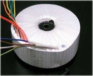
Transformers
Here are the transformers (DIYCable.com : Intro » Home » Exodus/Hypex Amps » Amp Parts »), I am looking. They are only $65.00 USA each and come with extra low power secondaries. But here are Antek's (https://www.antekinc.com/pdf/AN-10440.pdf) transfos. They are $100.00 USA. The diycable.com transfos are for their subwoofer amplifier and have 1amp lowpower secondaries (13-0-13 @ 1A and 0-16 @ 1A)while antek's are 0-12 @ 2A and 0-18 @ 2A. I would be saving $70.00 for the pair with diycable's, but the Antek's secondaries can push 2Amps. What do you think? I just wanted your opinion about which do you think would be the better transformer for the Krell, the soft-start and speaker protection and will need the 2 Amps?
Here are the transformers (DIYCable.com : Intro » Home » Exodus/Hypex Amps » Amp Parts »), I am looking. They are only $65.00 USA each and come with extra low power secondaries. But here are Antek's (https://www.antekinc.com/pdf/AN-10440.pdf) transfos. They are $100.00 USA. The diycable.com transfos are for their subwoofer amplifier and have 1amp lowpower secondaries (13-0-13 @ 1A and 0-16 @ 1A)while antek's are 0-12 @ 2A and 0-18 @ 2A. I would be saving $70.00 for the pair with diycable's, but the Antek's secondaries can push 2Amps. What do you think? I just wanted your opinion about which do you think would be the better transformer for the Krell, the soft-start and speaker protection and will need the 2 Amps?
Attachments
A Retired Nut
Thank you so much. I have learned so much from you guys, the books, and searching on the Internet. A nice hobby for a retired nut. Better than giving money away at the casino.Very nice boards spurlte 😉
@ Arick: Haha aiaiai, I can understand that 😀 I have fortunatelly not experienced a shock from the heatsinks. Hope it keeps this way 😉! Hmm, hope it keeps stable without ringing. If ringing realy gets out of control I maybe can isolate the trannies. I've red that especially MOSFETS suffer from oscillation due to large leads / ungrounded heatsinks and so on. Sice the trannies have a relative small Ft, I hope oscillation does not have a chance.
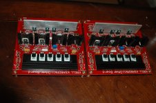
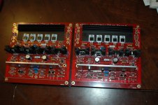
@ Spurtle: Great work David! Like the Dale resistors. I am thinking of changing the resistors on my boards to Dale resistors too. Keep up the good work 😉!
Ah, I see. The paralleled cap in the schematic of the ExtremA is the same as the x-capacitor we discussed earlier about. So the info I mailed earlier complies also to this cap 🙂 This is a common way to block sparks on the net. Sometimes you can hear a little spark when an inductive load is switched on elsewere in your house, like when the compressor of your fridge is turned on or something like that. This capacitor is called in Holland a ratelcondensator which means rattle capacitor. They are used big time in old tube radio's. Here you see one http://members.home.nl/schniermanni/470a/draad.jpg. This kind of capacitors are covered with tar. Very famous capacitors from Philips, we in Holland call them also tar bombs, because they sometimes explode haha. Due to the tar they are isolated from moisture, but... after more than 50 years they just arent relieable anymore. When you hear some hissing when you power up a radio which is not used for long time you know that your ratelcondensator is going to die 🙂 Then you have to cut the power very fast otherwise your rectifier tube and transformer will die too :-(.
@ Arick: Haha aiaiai, I can understand that 😀 I have fortunatelly not experienced a shock from the heatsinks. Hope it keeps this way 😉! Hmm, hope it keeps stable without ringing. If ringing realy gets out of control I maybe can isolate the trannies. I've red that especially MOSFETS suffer from oscillation due to large leads / ungrounded heatsinks and so on. Sice the trannies have a relative small Ft, I hope oscillation does not have a chance.
@ Spurtle: Great work David! Like the Dale resistors. I am thinking of changing the resistors on my boards to Dale resistors too. Keep up the good work 😉!Yes, they were suggested by Jim's Audio listed on parts list as "Dale RN60D." .07 cents US @ Mouser electronics, USA. Heard through the grape vine that these resistors run a tight ship therefore adhere the the intented circuitry. Oh, what do I know? I just follow the current suggestions. Have you seen the current Krell Evolution 403e and it's price? Wow. But it's rated a 400WPC @ 8ohms. Glad to be anywhere near that kind of money, cloned or not.
Ah, I see. The paralleled cap in the schematic of the ExtremA is the same as the x-capacitor we discussed earlier about. So the info I mailed earlier complies also to this cap 🙂 This is a common way to block sparks on the net. Sometimes you can hear a little spark when an inductive load is switched on elsewere in your house, like when the compressor of your fridge is turned on or something like that. This capacitor is called in Holland a ratelcondensator which means rattle capacitor. They are used big time in old tube radio's. Here you see one http://members.home.nl/schniermanni/470a/draad.jpg. This kind of capacitors are covered with tar. Very famous capacitors from Philips, we in Holland call them also tar bombs, because they sometimes explode haha. Due to the tar they are isolated from moisture, but... after more than 50 years they just arent relieable anymore. When you hear some hissing when you power up a radio which is not used for long time you know that your ratelcondensator is going to die 🙂 Then you have to cut the power very fast otherwise your rectifier tube and transformer will die too :-(.
Thanks for the tip David! I did not know Mouser sold these resistors. That is a nice price. Here in Holland there are webshops who dare to ask 1 euro per Dale resistor! Off course I want to pay for quality, but that price felt to me as a rip-off so. Turns out it was a rip-off indeed! Yup, the Dale RN60D are mil spec so very good quality 🙂.
:O That is a nice amplifier, but indeed expensive!!! Like the design, but for that amount of money I like a used BMW E90 3.20 even more haha ;-).
I have plans of making a Goldmund Nemesis 9.2 after this project. I have already spotted some, very rare, 2SJ49 / 2SK134 mosfets. That amplifier costed back in the days almost 33000 dollars. I felt almost from my chair when I saw that. I almost can't imagine the Goldmund company has that much overhead to ask this amount of money. Especially when you compaire the components which are good, but not that special nor expensive.
Dan D' Agostino left the Krell company. He started a new company instead. This is one of his latest amplifiers: Dan D'Agostino Discusses His New Momentum Monoblock Amplifier - YouTube
I REALY like the design of this amplifier. Especially the little, watch-like meter.
By the way, made some progress. I've made a little PCB with fuses for the secondairies (one fuse holder is missing, will be delivered next week):
Mounted some spacers to the heatsink:
So I could attach this plate which will protect the PCB's on top from radiation heat:
Maybe I mount another fan sideways to the heatsink to redirect radiation heat a bit.
And finaly how it should become (PCB's are not mounted right now):
:O That is a nice amplifier, but indeed expensive!!! Like the design, but for that amount of money I like a used BMW E90 3.20 even more haha ;-).
I have plans of making a Goldmund Nemesis 9.2 after this project. I have already spotted some, very rare, 2SJ49 / 2SK134 mosfets. That amplifier costed back in the days almost 33000 dollars. I felt almost from my chair when I saw that. I almost can't imagine the Goldmund company has that much overhead to ask this amount of money. Especially when you compaire the components which are good, but not that special nor expensive.
Dan D' Agostino left the Krell company. He started a new company instead. This is one of his latest amplifiers: Dan D'Agostino Discusses His New Momentum Monoblock Amplifier - YouTube
I REALY like the design of this amplifier. Especially the little, watch-like meter.
By the way, made some progress. I've made a little PCB with fuses for the secondairies (one fuse holder is missing, will be delivered next week):
An externally hosted image should be here but it was not working when we last tested it.
Mounted some spacers to the heatsink:
An externally hosted image should be here but it was not working when we last tested it.
So I could attach this plate which will protect the PCB's on top from radiation heat:
An externally hosted image should be here but it was not working when we last tested it.
Maybe I mount another fan sideways to the heatsink to redirect radiation heat a bit.
And finaly how it should become (PCB's are not mounted right now):
An externally hosted image should be here but it was not working when we last tested it.
- Home
- Amplifiers
- Solid State
- Stolen Trademark Amplifier from Jim's Audio on EBAY