Regarding SPDIF sync:
Input frequency of SPDIF in can be measured by the spdifrx_frame_sync and timers. Then the clock can be set for the same output frequency.
Sampling frequencies (input and output) change constantly depending on the crystal tempcos and such. You should monitor the output vs. input rate vs. buffer usage continuously and adjust the PLL on the fly (don't know is its even possible without stopping the I2S clock first) but the process could introduce some jitter. Also you would anyway have to use large buffers.
The best: asrc
Good solution: continious change
Good enough: estimate samplerate
Haven't seen any documentation on delay after changing i2s clock parameters
There are very good possibilities in the MCU to monitor and calculating input samplerate.
I dont think drift of a whole samplelength occurs that often in common spdif
Maybe you have some numbers?
Numbers, yes. A 10 ppm clock (quite a good one) can have a frequency variation of +/- 0.5 meaning in worst case (both two system clocks have 10 ppm crystal and drift fully apart) the difference might be exactly one sample / second.
10 ppm crystals are not that common, sound cards etc. might use 50 ppm crystals or even worse. Here's a handly calculator:
https://www.jitterlabs.com/support/calculators/ppm/
So a 50 ppm clock gives variation of +/- 2.4 Hz, that's almost five samples per second in worst case.
10 ppm crystals are not that common, sound cards etc. might use 50 ppm crystals or even worse. Here's a handly calculator:
https://www.jitterlabs.com/support/calculators/ppm/
So a 50 ppm clock gives variation of +/- 2.4 Hz, that's almost five samples per second in worst case.
Word Clock – What’s the difference between jitter and frequency drift?|Apogee KnowledgeBase
This is statistics also, worst case do not happen every time
Think 2,5hz variation would be very anoying
This is statistics also, worst case do not happen every time
Think 2,5hz variation would be very anoying
Stm32-audio100a . For 48khz prosessing
Asrc included. Find no 1:1 asrc though. Maybe I did not find it and its there
I think the spdif module take care of short time jitter. Figure 344 in rm0390
Earlier posts from me is about long term drift
Asrc included. Find no 1:1 asrc though. Maybe I did not find it and its there
I think the spdif module take care of short time jitter. Figure 344 in rm0390
Earlier posts from me is about long term drift
Stm32-audio100a . For 48khz prosessing
Asrc included. Find no 1:1 asrc though. Maybe I did not find it and its there
I think the spdif module take care of short time jitter. Figure 344 in rm0390
Earlier posts from me is about long term drift
STM-audio100a is software library for fixed ratio convertions.
Figure 344 describes locking to S/PDIF stream (starting from preamble detection and so on).
Anyway, as you can monitor spdif frame rate and compare it to output rate you could (quite easily I think) implement software control for output using VCXO as an oscillator. See http://www.vectron.com/products/literature_library/VCXO.pdf for an example. Requires some hacking and is probably locked to a single sample rate/VCXO.
An example of VCXO:
LF VCXO026156 - IQD FREQUENCY PRODUCTS - VCXO, CFPV-45, 20M, SMD 7X5 | Farnell element14
Those are quite expensive. Above is only 100 ppm unit.
Hm. Still think Figure 344 shows the strategy for exclude short time jitter of input (27.3.3)
Then medium frequency and frequency drift must be calculated with spdifrx_frame_sync and timers.
Do not understand how short time jitter can survive the SPDIFRX.
I do also not understand why lag/buffering should be larger than a frame when syncing to spdifrx_frame_sync. So a few frames should be sufficient.
Interesting idea with outside loop for syncing.
Do you know what ST Source Rate Converter in page 47of http://www.st.com/st-web-ui/static/...on/stm32-stm8_embedded_software_solutions.pdf is?
Regards Torgeir
Regarding sync: http://www.st.com/st-web-ui/static/...ical/document/application_note/DM00154959.pdf
2.5 Communication interfaces block 2.5.1 From SPDIFRX to TIM SPDIFRX (SPDIFRX_FRAME_SYNC) is connected to TIM11_CH1 to measure the clock drift of received SPDIFRX frames. This interconnection is explained in the section “TIM11 option register 1 (TIM11_OR)” of the RM0390 reference manual.
2.5 Communication interfaces block 2.5.1 From SPDIFRX to TIM SPDIFRX (SPDIFRX_FRAME_SYNC) is connected to TIM11_CH1 to measure the clock drift of received SPDIFRX frames. This interconnection is explained in the section “TIM11 option register 1 (TIM11_OR)” of the RM0390 reference manual.
Caution: The software has to set these bits correctly to ensure that the VCO input frequency
ranges from 1 to 2 MHz. It is recommended to select a frequency of 2 MHz to limit
PLL jitter.
VCO input frequency = PLL input clock frequency / PLLM with 2 ≤ PLLM ≤ 63
Bits 14:6 PLLN[8:0]: Main PLL (PLL) multiplication factor for VCO
Set and cleared by software to control the multiplication factor of the VCO. These bits can
be written only when PLL is disabled. Only half-word and word accesses are allowed to
write these bits.
Caution: The software has to set these bits correctly to ensure that the VCO output
frequency is between 100 and 432 MHz. Below an example of PLLN bitfield
forbidden values for PLL input equal to FPLL_IN = 1 MHz:
VCO output frequency = VCO input frequency × PLLN with 192 ≤ PLLN ≤ 432
From 6.3.2 RCC PLL configuration register (RCC_PLLCFGR) of RM0390
from 26.6.3 Clock generatorWhen the master clock is generated (MCKOE in the SPIx_I2SPR register is set):
fS = I2SxCLK / [(16*2)*((2*I2SDIV)+ODD)*8)] when the channel frame is 16-bit wide
fS = I2SxCLK / [(32*2)*((2*I2SDIV)+ODD)*4)] when the channel frame is 32-bit wide
When the master clock is disabled (MCKOE bit cleared):
fS = I2SxCLK / [(16*2)*((2*I2SDIV)+ODD))] when the channel frame is 16-bit wide
fS = I2SxCLK / [(32*2)*((2*I2SDIV)+ODD))] when the channel frame is 32-bit wide
1< I2SDIV < 255
And I2SxCLK is
VCO output frequency = VCO input frequency × PLLN with 192 ≤ PLLN ≤ 432
VCO input frequency = PLL input clock frequency / PLLM with 2 ≤ PLLM ≤ 63
So quite a few possible Fs
The relevant frequencies must be precalculated with the closest other frequencies also calculated. (can be total different sets of PLLM, PLLN, PLLR, I2SDIV and ODD)
from 26.6.3 Clock generatorWhen the master clock is generated (MCKOE in the SPIx_I2SPR register is set):
fS = I2SxCLK / [(16*2)*((2*I2SDIV)+ODD)*8)] when the channel frame is 16-bit wide
fS = I2SxCLK / [(32*2)*((2*I2SDIV)+ODD)*4)] when the channel frame is 32-bit wide
When the master clock is disabled (MCKOE bit cleared):
fS = I2SxCLK / [(16*2)*((2*I2SDIV)+ODD))] when the channel frame is 16-bit wide
fS = I2SxCLK / [(32*2)*((2*I2SDIV)+ODD))] when the channel frame is 32-bit wide
1< I2SDIV < 255
And I2SxCLK is
VCO output frequency = VCO input frequency × PLLN with 192 ≤ PLLN ≤ 432
VCO input frequency = PLL input clock frequency / PLLM with 2 ≤ PLLM ≤ 63
So quite a few possible Fs
The relevant frequencies must be precalculated with the closest other frequencies also calculated. (can be total different sets of PLLM, PLLN, PLLR, I2SDIV and ODD)
That will not work, you will not be able to lock to incoming S/PDIF by "estimating" sample rate, adjusting those parameters is too coarse.
VCXO isn't actually that hard. Tentlabs have proper VCXO's for audio frequencies (11.2896 MHz for 44.1 kHz and so on, see VCXO ). You use the VCXO output as the SAIxEXTCLK signal.
Regarding software implementation just calculate the difference in received samples (timer connected to spdif frame clock configured as counter) in DMA half buffer callback, and for an example if SPDIF count is bigger than I2S count then increase the control voltage to VCXO (sent from PWM or DAC output) by one number (if using an 8-bit DAC for an example). That way I2S sample rate will catch the SPDIF rate eventually. You will need to use a little bit larger DMA buffers though than would be ideal (OK for listening music).
Last edited:
I dont think it is too coarce
And it is ST strategy for using Spdif
27.3 and 27.4
I see ST has several registers they think is suitable to estimate the input samplerate on a semi fine way.
27.5.3 with5 16bits
27.5.9 TLO and THI 13 bits
I guess it is already several working solutions out there.
The resolution of output SR can be calculated. That will deside the length of needed buffer
Regarding SPDIF sync:
...
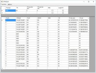
The picture shows thet there are quite som divisions that can give a almost exact mach of frequencies. In addition samples can be replicated on zero crossing when needed.
"Almost exact match" is not enough, and estimating it once isn't enough. Take a real SPDIF receiver and a frequency counter and give STM32Cubemx a shot. I'm not the man from La Mancha, but if you get the job done using those bare integer dividers and multiplier let us know.
Even if I think it is possible to go to the moon, it don't mean I can do it myself🙂
But I have thought about of making a program to calculate possible frequencies around the normal samplefequencies. I tried so google such a calculator, but could not find one.
Thought about your case of 50ppm drift. That should be 5 samples a second for 100k SF.
So the SF delta must be possible to adjust 50ppm or a puffer that handles 5 new samples each second must be set up.
This can't go on forever so my startegy depends on that samplerate can be changed without droppout artifacts.
I see ST recomends to check input receive status every 0.1 seconds.
27.4:
– The software has to check from time to time (i.e. every 100 ms for example) if the
SPDIFRX can find synchronization. This can be done by checking if the bit TERR
is set. When it is set it indicates that no activity as been found.
This is maybe a nice interval to check number of buffered samples and clockdrift.
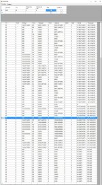
The picture shows different possible FS values inside 100ppm of 48k.
That is max 20 samples/sek drift. So drift can be much lover than that.
About 30 ppm resolution or 6 samples/sec
That is max 20 samples/sek drift. So drift can be much lover than that.
About 30 ppm resolution or 6 samples/sec
Attachments
Last edited:

And I guess 2.4 Mhz SR is a little optimistic. Maybe 400k?
So 7 * 3 = 21 is more realistic. Ends up at about 90 dB SNR. Still an OK number for bass and this pricelevel. High harmonics under 150Hz is no problem in my opinion using ordinary (sub 200$) bass elements.
See the ADC dynamic accuracy (STM32F446) is better than expected.:
Table 79. ADC dynamic accuracy at fADC = 36 MHz - limited test conditions
VDDA = VREF+ = 3.3 V
Input Frequency = 20 KHz
SINAD Signal-to noise and distortion ratio 66 67 -
SNR Signal-to noise ratio 64 68 - dB
THD Total harmonic distortion -70 -72 - dB
And it looks like 2.4MHz is doable.
So maybe almost 100dB at 2.4k SF is possible after all.
Sorry forgot to devide with R.
Then there is more options still.
ST gave a advice how to switch between output frequencies in a "safe way"
"Hi torgeirs,
So can the PLL be disabled, changed and enabled between two samples?
Disabling and reconfiguring PLL between two samples is insecure, according to datasheet the PLL lock time ~200µs.
So you can configure two PLLs: PLLR and the PLLI2S to generate different clocks and then switch between them .
-Syrine-"
Attachments
I dont think it is too coarce
And it is ST strategy for using Spdif
27.3 and 27.4
I see ST has several registers they think is suitable to estimate the input samplerate on a semi fine way.
27.5.3 with5 16bits
27.5.9 TLO and THI 13 bits
I guess it is already several working solutions out there.
The resolution of output SR can be calculated. That will deside the length of needed buffer
So the stretegy can be to:
Measure input samplerate with with5 or TLO and THI or spdifrx_frame_sync and timers.
Set PLLR to closest samplerate.
Every 0.1 second: Measure input samplerate with spdifrx_frame_sync and timers.
If buffer to small or input/output difference can be smaller find new output samplerate and set PLLI2S.
When PLLI2S has settled switch output clocksource.
At next adjustment, set and switch to PLLR and so on.
To me it looks like a swing of about 100ppm is doable. That is 10 samples at 100k samplefrequency. And 0.1 ms delay.
Maybe around 1 ms buffer is safer...
Then a very cheap digital volumcontrol or SPDIF to I2S can be implemented.
ST too have M7 Cortex ARM MCU (running at 216MHZ) for a few moths with a discovery kit (eval board) for only a 55$ buck board with display attached.
I think even better than ATMEL...but i dont know ATMEL enough.
32F746GDISCOVERY Discovery kit with STM32F746NG MCU - STMicroelectronics
ST has now come up with 144 pin verson of nucleo.
Both M7 and M446.
Very reasonable priced at 19 and 23 USD
Should be great for 2xi2S or Multichannel multiplexed outputs
- Home
- Source & Line
- Digital Line Level
- STM 32 F4 Discovery and Audioweaver, anyone tried?